
Datasheet

www.vishay.com For technical questions, contact: diodestech@vishay.com
Document Number: 94317
2 Revision: 05-Mar-10
VS-MBRS130LTRPbF
Vishay High Power Products
Schottky Rectifier, 1.0 A
Note
(1)
Pulse width < 300 μs, duty cycle < 2 %
Notes
(1)
thermal runaway condition for a diode on its own heatsink
(2)
Mounted 1" square PCB
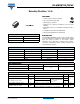
ELECTRICAL SPECIFICATIONS
PARAMETER SYMBOL TEST CONDITIONS VALUES UNITS
Maximum forward voltage drop V
FM
(1)
1 A
T
J
= 25 °C
0.420
V
2 A 0.470
1 A
T
J
= 125 °C
0.300
2 A 0.370
Maximum reverse leakage current I
RM
(1)
T
J
= 25 °C
V
R
= Rated V
R
1
mAT
J
= 100 °C 10
T
J
= 125 °C 20
Maximum junction capacitance C
T
V
R
= 5 V
DC
(test signal range 100 kHz to 1 MHz), 25 °C 200 pF
Typical series inductance L
S
Measured lead to lead 5 mm from package body 2.0 nH
Maximum voltage rate of change dV/dt Rated V
R
10 000 V/μs
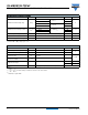
THERMAL - MECHANICAL SPECIFICATIONS
PARAMETER SYMBOL TEST CONDITIONS VALUES UNITS
Maximum junction temperature range T
J
(1)
- 55 to 125
°C
Maximum storage temperature range T
Stg
- 55 to 150
Maximum thermal resistance,
junction to lead
R
thJL
(2)
DC operation
See fig. 4
25
°C/W
Maximum thermal resistance,
junction to ambient
R
thJA
DC operation 80
Approximate weight
0.10 g
0.003 oz.
Marking device Case style SMB (similar to DO-214AA) V13L
dP
tot
dT
J
-------------
1
R
thJA
--------------<