
Datasheet

MBR10Hxx, MBRF10Hxx, MBRB10Hxx
www.vishay.com
Vishay General Semiconductor
Revision: 20-Jan-14
3
Document Number: 88667
For technical questions within your region: DiodesAmericas@vishay.com
, DiodesAsia@vishay.com, DiodesEurope@vishay.com
THIS DOCUMENT IS SUBJECT TO CHANGE WITHOUT NOTICE. THE PRODUCTS DESCRIBED HEREIN AND THIS DOCUMENT
ARE SUBJECT TO SPECIFIC DISCLAIMERS, SET FORTH AT www.vishay.com/doc?91000
RATINGS AND CHARACTERISTICS CURVES (T
C
= 25 °C unless otherwise noted)
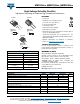
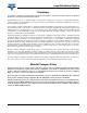
Fig. 1 - Forward Current Derating Curve
Fig. 2 - Maximum Non-Repetitive Peak Forward Surge Current
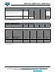
Fig. 3 - Typical Instantaneous Forward Characteristics
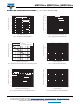
Fig. 4 - Typical Reverse Characteristics
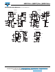
Fig. 5 - Typical Junction Capacitance
Fig. 6 - Typical Transient Thermal Impedance
0
4
8
12
20
0
50
100
150
16
180
MBRF
Resistive or Inductive Load
Average Forward Current (A)
Case Temperature (°C)
MBR, MBRB
0
50
150
100
250
200
300
1
100
10
T
J
= T
J
Max.
8.3 ms Single Half Sine-Wave
Number of Cycles at 60 Hz
Peak Forward Surge Current (A)
0.1 0.2 0.6 0.7 0.8 0.90.3
100
10
0.1
0.01
1.0
0.4 0.5
1.0
Instantaneous Forward Voltage (V)
Instantaneous Forward Current (A)
T
J
= 100 °C
T
J
= 150 °C
T
J
= 125 °C
T
J
= 175 °C
T
J
= 25 °C
1
1000
0.01
0.1
10 000
100
10
20 10040 60 80
Percent of Rated Peak Reverse Voltage (%)
Instantaneous Reverse Current (µA)
T
J
= 100 °C
T
J
= 150 °C
T
J
= 125 °C
T
J
= 25 °C
0.1
101
100
1000
10 000
10
100
Reverse Voltage (V)
Junction Capacitance (pF)
0.01
0.1 1
10
10
100
0.1
1
t - Pulse Duration (s)
Transient Thermal Impedance (°C/W)