
Datasheet

MBRA140TR
Bulletin PD-20582 rev. C 03/03
2
www.irf.com
Part number MBRA140TR
V
R
Max. DC Reverse Voltage (V)
V
RWM
Max. Working Peak Reverse Voltage (V)
40
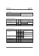
Voltage Ratings
Absolute Maximum Ratings
V
FM
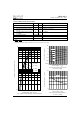
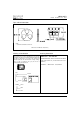
Max. Forward Voltage Drop (1) 0.55 V @ 1A
* See Fig. 1 0.71 V @ 2A
0.5 V @ 1A
0.65 V @ 2A
0.49 V @ 1A
0.63 V @ 2A
I
RM
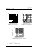
Max. Reverse Leakage Current (1) 0.5 mA T
J
= 25 °C
* See Fig. 2 10 mA T
J
= 100 °C V
R
= rated V
R
26 mA T
J
= 125 °C
V
F(TO)
Threshold Voltage 0.36 V T
J
= T
J
max.
r
t
Forward Slope Resistance 104 m Ω
C
T
Typical Junction Capacitance 38 pF V
R
= 10V
DC
, T
J
= 25°C, test signal = 1Mhz
L
S
Typical Series Inductance 2.0 nH Measured lead to lead 5mm from package body
dv/dt Max. Voltage Rate of Change 10000 V/ µs (Rated V
R
)
T
J
= 25 °C
T
J
= 100 °C
Electrical Specifications
Parameters Value Units Conditions
(1) Pulse Width < 300µs, Duty Cycle < 2%
T
J
= 125 °C
I
F(AV)
Max. Average Forward Current 1.0 A 50% duty cycle @ T
L
= 118 °C, rectangular wave form.
* See Fig. 4 On PC board 9mm
2
island (.013mm thick copper pad area)
I
FSM
Max. Peak One Cycle Non-Repetitive 120 5µs Sine or 3µs Rect. pulse
Surge Current * See Fig. 6 30 10ms Sine or 6ms Rect. pulse
E
AS
Non-Repetitive Avalanche Energy 3.0 mJ T
J
= 25 °C, I
AS
= 1A, L = 6mH
I
AR
Repetitive Avalanche Current 1.0 A
Parameters Value Units Conditions
A
Following any rated
load condition and
with rated V
RRM
applied