
Datasheet


MBR735/ MBR745, MBRB735/ MBRB745
Bulletin PD-2.325 rev. E 01/03
2
www.irf.com
V
R
Max. DC Reverse Voltage (V) 35 45
V
RWM
Max. Working Peak Reverse Voltage (V)
Voltage Ratings
Parameters MBR.735 MBR.745
I
F(AV)
Max. Average Forward Current 7.5 A @ T
C
= 131 °C (Rated V
R
)
I
FSM
Non-Repetitive Peak Surge Current 690 A 5µs Sine or 3µs Rect. pulse
150 Surge applied at rated load condition halfwave single
phase 60Hz
E
AS
Non-Repetitive Avalanche Energy 7 mJ T
J
= 25 °C, I
AS
= 2 Amps, L = 3.5 mH
I
AR
Repetitive Avalanche Current 2 A Current decaying linearly to zero in 1 µsec
Frequency limited by T
J
max. V
A
= 1.5 x V
R
typical
Absolute Maximum Ratings
Parameters MBR.. Conditions
Following any rated load
condition and with rated
V
RRM
applied
V
FM
Max. Forward Voltage Drop(1) 0.84 V @ 15A T
J
= 25 °C
0.57 V @ 7.5A T
J
= 125 °C
0.72 V @ 15A
I
RM
Max. Instantaneus Reverse Current 0.1 mA T
J
= 25 °C Rated DC voltage
(1) 15 mA T
J
= 125 °C
C
T
Max. Junction Capacitance 400 pF V
R
= 5V
DC
, (test signal range 100Khz to 1Mhz) 25°C
L
S
Typical Series Inductance 8.0 nH Measured from top of terminal to mounting plane
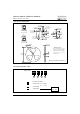
dv/dt Max. Voltage Rate of Change 1000 V/ µs
(Rated V
R
)
Electrical Specifications
Parameters MBR.. Conditions
(1) Pulse Width < 300µs, Duty Cycle <2%
Thermal-Mechanical Specifications
Parameters MBR.. Conditions
Kg-cm
(Ibf-in)
T
J
Max. Junction Temperature Range - 65 to 150 °C
T
stg
Max. Storage Temperature Range - 65 to 17 5 °C
R
thJC
Max. Thermal Resistance Junction 3.0 °C/W DC operation
to Case
R
thCS
Typical Thermal Resistance, Case 0.50 °C/W Mounting surface, smooth and greased
to Heatsink
wt Approximate Weight 2 (0.07) g (oz.)
T Mounting Torque Min. 6 (5)
Max. 12 (10
Units
Units
Units