
Datasheet
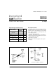

MBR350, MBR360
Bulletin PD-20594 rev. B 03/03
2
www.irf.com
T
J
Max. Junction Temperature Range(*) -40 to 150 °C
T
stg
Max. Storage Temperature Range -40 to 150 °C
R
thJL
Typical Thermal Resistance Junction 30 °C/W DC operation (* See Fig. 4)
to Lead (**)
wt Approximate Weight 1.2 (0.042) g (oz.)
Case Style C - 16
I
F(AV)
Max. Average Forward Current 3.0 A 50% duty cycle @ T
L
= 50°C, rectangular wave form
* See Fig. 4
I
FSM
Max. Peak One Cycle Non-Repetitive 460 5µs Sine or 3µs Rect. pulse
Surge Current * See Fig. 6 80 10ms Sine or 6ms Rect. pulse
E
AS
Non-Repetitive Avalanche Energy 5.0 mJ T
J
= 25 °C, I
AS
= 1 Amps, L = 10 mH
I
AR
Repetitive Avalanche Current 1.0 A Current decaying linearly to zero in 1 µsec
Frequency limited by T
J
max. V
A
= 1.5 x V
R
typical
Part number MBR350 MBR360
V
R
Max. DC Reverse Voltage (V)
V
RWM
Max. Working Peak Reverse Voltage (V)
Voltage Ratings
50 60
Thermal-Mechanical Specifications
V
FM
Max. Forward Voltage Drop 0.58 V @ 1.0A
* See Fig. 1 (1) 0.73 V @ 3.0A T
J
= 25 °C
1.06 V @ 9.4A
0.49 V @ 1.0A
0.64 V @ 3.0A T
J
= 125 °C
0.89 V @ 9.4A
I
RM
Max. Reverse Leakage Current 0.6 mA T
J
= 25 °C
* See Fig. 2 (1) 8 mA T
J
= 100 °C V
R
= rated V
R
15 mA T
J
= 125 °C
C
T
Typical Junction Capacitance 190 pF V
R
= 5V
DC
(test signal range 100Khz to 1Mhz) 25°C
L
S
Typical Series Inductance 9.0 nH Measured lead to lead 5mm from package body
dv/dt Max. Voltage Rate of Change 10000 V/µs (Rated V
R
)
Electrical Specifications
(1) Pulse Width < 300µs, Duty Cycle <2%
Parameters Value Units Conditions
Parameters Value Units Conditions
(**) Mounted 1 inch square PCB, thermal probe connected to lead 2mm from package
Absolute Maximum Ratings
Following any rated
load condition and with
rated V
RRM
applied
A
Parameters Value Units Conditions
< thermal runaway condition for a diode on its own heatsink
(*) dPtot 1
dTj Rth( j-a)