
Datasheet


MBR10xx, MBRF10xx & MBRB10xx Series
Vishay Semiconductors
formerly General Semiconductor
Document Number 88669 www.vishay.com
1-Jul-02 3
0
50
100
150
2
4
6
8
10
12
0.1
1
10
100
25
50
75
125
150
175
0.01
0.1
1
10
100
0.1
10.0
0.1
1
10
100
100
1,000
4,000
100
100
1
0
0
20
40
60
80
100
0.001
0.01
0.1
1
10
20
0
0.2
0.4
0.6
0.8
1.0
1.2
0.01
0.1
1
10
50
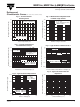
Fig. 1 - Forward Current
Derating Curve
Fig. 3 - Typical Instantaneous
Forward Characteristics
Fig. 5 - Typical Junction Capacitance
Fig. 2 - Maximum Non-Repetitive Peak
Forward Surge Current
Fig. 4 - Typical Reverse Characteristics
Fig. 6 - Typical Transient Thermal
Impedance
Case Temperature (°C)
Average Forward Current (A)
Instantaneous Forward Voltage (V)
Instantaneous Forward Current (A)
Instantaneous Reverse Current (mA)
Reverse Voltage (V)
Junction Capacitance (pF)
Percent of Rated Peak Reverse Voltage (%)
t, Pulse Duration (sec.)
Transient Thermal Impedance (°C/W)
Number of Cycles at 60 Hz
Peak Forward Surge Current (A)
Resistive or Inductive Load
T
J
= T
J
max.
8.3ms single half sine-wave
(JEDEC method)
Pulse Width = 300µs
1% Duty Cycle
T
J
= 150°C
T
J
= 25°C
T
J
= 25°C
T
J
= 125°C
T
J
= 75°C
MBR1635 - MBR1645
MBR1650 - MBR1660
MBR1635 - MBR1645
MBR1650 - MBR1660
MBR1635 - MBR1645
MBR1650 - MBR1660
MBR1635 - MBR1645
MBR1650 - MBR1660
T
J
= 25°C
f = 1.0 MHz
Vsig = 50mVp-p
Ratings and
Characteristic Curves (T
A
= 25°C unless otherwise noted)