
Datasheet


MBR10xx, MBRF10xx & MBRB10xx Series
Vishay Semiconductors
formerly General Semiconductor
Document Number 88669 www.vishay.com
1-Jul-02 1
Schottky Barrier Rectifier
Reverse Voltage 35 to 60V
Forward Current 10A
0.08
(2.032)
0.24
(6.096)
0.42
(10.66)
0.63
(17.02)
0.12
(3.05)
0.33
(8.38)
Mounting Pad Layout TO-263AB
0.380 (9.65)
0.411 (10.45)
0.320 (8.13)
0.360 (9.14)
0.591 (15.00)
0.624 (15.85)
1
2
0.245 (6.22)
MIN
K
0.027 (0.686)
0.037 (0.940)
0.105 (2.67)
0.095 (2.41)
0.205 (5.20)
0.195 (4.95)
K
0.160 (4.06)
0.190 (4.83)
0.045 (1.14)
0.055 (1.40)
0.021 (0.53)
0.014 (0.36)
0.110 (2.79)
0.140 (3.56)
0.090 (2.29)
0.110 (2.79)
0.047 (1.19)
0.055 (1.40)
PIN 1
PIN 2
K - HEATSINK
0-0.01 (0-0.254)
0.060 (1.52)
0.405 (10.27)
0.383 (9.72)
0.191 (4.85)
0.171 (4.35)
0.600 (15.5)
0.580 (14.5)
0.560 (14.22)
0.530 (13.46)
0.037 (0.94)
0.027 (0.69)
0.140 (3.56)
0.130 (3.30)
0.350 (8.89)
0.330 (8.38)
0.188 (4.77)
0.172 (4.36)
0.110 (2.80)
0.100 (2.54)
0.131 (3.39)
0.122 (3.08)
0.110 (2.80)
0.100 (2.54)
0.022 (0.55)
0.014 (0.36)
0.205 (5.20)
0.195 (4.95)
12
PIN
DIA.
DIA.
PIN 1
PIN 2
0.676 (17.2)
0.646 (16.4)
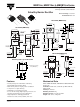
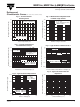
ITO-220AC (MBRF10xx)
TO-220AC (MBR10xx)
Dimensions in inches
and (millimeters)
TO-263AB (MBRB10xx)
0.154 (3.91)
0.148 (3.74)
DIA.
0.113 (2.87)
0.103 (2.62)
0.185 (4.70)
0.175 (4.44)
0.055 (1.39)
0.045 (1.14)
0.145 (3.68)
0.135 (3.43)
0.350 (8.89)
0.330 (8.38)
0.160 (4.06)
0.140 (3.56)
0.037 (0.94)
0.027 (0.68)
0.205 (5.20)
0.195 (4.95)
0.560 (14.22)
0.530 (13.46)
0.022 (0.56)
0.014 (0.36)
0.110 (2.79)
0.100 (2.54)
12
1.148 (29.16)
1.118 (28.40)
0.105 (2.67)
0.095 (2.41)
0.410 (10.41)
0.390 (9.91)
0.635 (16.13)
0.625 (15.87)
0.603 (15.32)
0.573 (14.55)
PIN
0.415 (10.54) MAX.
PIN 1
PIN 2
CASE
0.370 (9.40)
0.360 (9.14)
Mechanical Data
Case: JEDEC TO-220AC, ITO-220AC & TO-263AB molded
plastic body
Terminals: Plated leads, solderable per MIL-STD-750,
Method 2026
Polarity: As marked
Mounting Position: Any
Mounting Torque: 10 in-lbs maximum
Weight: 0.08 ounce, 2.24 grams
Features
• Plastic package has Underwriters Laboratory
Flammability Classifications 94V-0
• Metal silicon junction, majority carrier conduction
• Low power loss, high efficiency
• Guardring for overvoltage protection
• For use in low voltage, high frequency inverters, free
wheeling, and polarity protection applications
• High temperature soldering guaranteed:
250°C/10 seconds, 0.25" (6.35mm) from case