
Datasheet

MBR10xxx-E3, MBRF10xxx-E3, MBRB10xxx-E3
www.vishay.com
Vishay General Semiconductor
Revision: 11-Sep-13
2
Document Number: 89034
For technical questions within your region: DiodesAmericas@vishay.com
, DiodesAsia@vishay.com, DiodesEurope@vishay.com
THIS DOCUMENT IS SUBJECT TO CHANGE WITHOUT NOTICE. THE PRODUCTS DESCRIBED HEREIN AND THIS DOCUMENT
ARE SUBJECT TO SPECIFIC DISCLAIMERS, SET FORTH AT www.vishay.com/doc?91000
Notes
(1)
Pulse test: 300 μs pulse width, 1 % duty cycle
(2)
Pulse test: Pulse width 40 ms
RATINGS AND CHARACTERISTICS CURVES (T
A
= 25 °C unless otherwise noted)
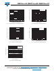
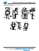
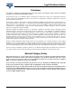
Fig. 1 - Forward Current Derating Curve Fig. 2 - Maximum Non-Repetitive Peak Forward Surge Current
ELECTRICAL CHARACTERISTICS (T
A
= 25 °C unless otherwise noted)
PARAMETER TEST CONDITIONS SYMBOL MAX. UNIT
Maximum instantaneous forward voltage
I
F
= 10 A T
C
= 25 °C
V
F
(1)
0.80
VI
F
= 10 A T
C
= 125 °C 0.65
I
F
= 20 A T
C
= 125 °C 0.75
Maximum reverse current per at working peak
reverse voltage
T
J
= 25 °C
I
R
(2)
100 µA
T
J
= 125 °C 6.0 mA
THERMAL CHARACTERISTICS (T
A
= 25 °C unless otherwise noted)
PARAMETER SYMBOL MBR MBRF MBRB UNIT
Typical thermal resistance
R
JA
60 - 60
°C/W
R
JC
2.0 3.5 2.0
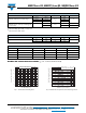
ORDERING INFORMATION (Example)
PACKAGE PREFERRED P/N UNIT WEIGHT (g) PACKAGE CODE BASE QUANTITY DELIVERY MODE
TO-220AC MBR10100CT-E3/4W 1.845 4W 50/tube Tube
ITO-220AC MBRF10100CT-E3/4W 1.661 4W 50/tube Tube
TO-263AB MBRB10100CT-E3/4W 1.384 4W 50/tube Tube
TO-263AB MBRB10100CT-E3/8W 1.384 8W 800/reel Tape and reel
0
2
4
6
10
0
50
100
150
8
Average Forward Current (A)
Case Temperature (°C)
Resistive or Inductive Load
40
60
100
80
140
120
160
1
100
10
T
J
= T
J
max.
8.3 ms Single Half Sine-Wave
Number of Cycles at 60 Hz
Peak Forward Surge Current (A)