
Datasheet

LS4148, LS4448
www.vishay.com
Vishay Semiconductors
Rev. 2.0, 14-Jul-17
1
Document Number: 85561
For technical questions within your region: DiodesAmericas@vishay.com
, DiodesAsia@vishay.com, DiodesEurope@vishay.com
THIS DOCUMENT IS SUBJECT TO CHANGE WITHOUT NOTICE. THE PRODUCTS DESCRIBED HEREIN AND THIS DOCUMENT
ARE SUBJECT TO SPECIFIC DISCLAIMERS, SET FORTH AT www.vishay.com/doc?91000
Small Signal Fast Switching Diodes
DESIGN SUPPORT TOOLS click logo to get started
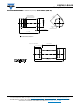
MECHANICAL DATA
Case: QuadroMELF (SOD-80)
Weight: approx. 34 mg
Cathode band color: black
Packaging codes / options:
GS18/10K per 13" reel (8 mm tape), 10K/box
GS08/2.5K per 7" reel (8 mm tape), 12.5K/box
FEATURES
• Silicon epitaxial planar diodes
• Electrical data identical with the devices 1N4148
and 1N4448 respectively
• QuadroMELF package
• AEC-Q101 qualified
• Material categorization: for definitions of compliance
please see www.vishay.com/doc?99912
APPLICATIONS
• Extremely fast switches
Available
Models
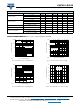
PARTS TABLE
PART TYPE DIFFERENTIATION ORDERING CODE
TYPE
MARKING
CIRCUIT
CONFIGURATION
REMARKS
LS4148 V
F
= max. 1000 mV at I
F
= 50 mA LS4148-GS18 or LS4148-GS08 - Single Tape and reel
LS4448 V
F
= max. 1000 mV at I
F
= 100 mA LS4448GS18 or LS4448GS08 - Single Tape and reel
ABSOLUTE MAXIMUM RATINGS (T
amb
= 25 °C, unless otherwise specified)
PARAMETER TEST CONDITION SYMBOL VALUE UNIT
Repetitive peak reverse voltage V
RRM
100 V
Reverse voltage V
R
75 V
Peak forward surge current t
p
= 1 μs I
FSM
2A
Repetitive peak forward current I
FRM
500 mA
Forward continuous current I
F
300 mA
Average forward current V
R
= 0 I
F(AV)
150 mA
Power dissipation P
tot
500 mW
THERMAL CHARACTERISTICS (T
amb
= 25 °C, unless otherwise specified)
PARAMETER TEST CONDITION SYMBOL VALUE UNIT
Thermal resistance junction to ambient air
On PC board
50 mm x 50 mm x 1.6 mm
R
thJA
300 K/W
Junction temperature T
j
175 °C
Storage temperature range T
stg
-65 to +175 °C