
Datasheet

KBL005, KBL01, KBL02, KBL04, KBL06, KBL08, KBL10
www.vishay.com
Vishay General Semiconductor
Revision: 30-Jan-2019
2
Document Number: 88655
For technical questions within your region: DiodesAmericas@vishay.com
, DiodesAsia@vishay.com, DiodesEurope@vishay.com
THIS DOCUMENT IS SUBJECT TO CHANGE WITHOUT NOTICE. THE PRODUCTS DESCRIBED HEREIN AND THIS DOCUMENT
ARE SUBJECT TO SPECIFIC DISCLAIMERS, SET FORTH AT www.vishay.com/doc?91000
Notes
(1)
Thermal resistance from junction to ambient with units mounted on 3.0" x 3.0" x 0.11" thick (7.5 cm x 7.5 cm x 0.3 cm) aluminum plate
(2)
Thermal resistance from junction to lead with units mounted on PCB at 0.375" (9.5 mm) lead length and 0.5" x 0.5" (12 mm x 12 mm) copper
pads
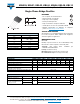
RATINGS AND CHARACTERISTICS CURVES (T
A
= 25 °C unless otherwise noted)
Fig. 1 - Derating Curve Output Rectified Current
Fig. 2 - Maximum Non-Repetitive Peak Forward Surge Current
Per Diode
Fig. 3 - Typical Instantaneous Forward Characteristics Per Diode
Fig. 4 - Typical Reverse Leakage Characteristics Per Diode
THERMAL CHARACTERISTICS (T
A
= 25 °C unless otherwise noted)
PARAMETER SYMBOL KBL005 KBL01 KBL02 KBL04 KBL06 KBL08 KBL10 UNIT
Typical thermal resistance
R
JA
(2)
19
°C/W
R
JL
(1)
4.0
ORDERING INFORMATION (Example)
PREFERRED P/N UNIT WEIGHT (g) PREFERRED PACKAGE CODE BASE QUANTITY DELIVERY MODE
KBL06-E4/51 6.0 51 300 Anti-static PVC tray
Temperature (°C)
Average Forward Current (A)
0
50
100
150
0
1.0
2.0
3.0
4.0
PCB Mounting
0.375" (9.5 mm) Lead Length
60 Hz Resistive or Inductive Load
Heatsink Mounted
3.0" sq .x 0.06" Thickness
(7. 5x 0.15 cm) Copper Plate
1
10
100
25
50
75
100
125
150
175
200
T
J
= 150 °C
Single Sine-Wave
Number of Cycles at 60 Hz
Peak Forward Surge Current (A)
1.0 Cycle
Instantaneous Forward Voltage (V)
Instantaneous Forward Current (A)
0.6
0.7
100
10
1
0.1
0.8
0.9
1.0
1.1
1.2
1.3
T
J
= 25 °C
Pulse Width = 300 µs
1 % Duty Cycle
0
20
40
60
80
100
0.01
0.1
1
10
Percent of Rated Peak Reverse Voltage (%)
Instantaneous Reverse Current (µA)
T
J
= 100 °C
T
J
= 25 °C