
Datasheet


5–5
ILD/Q615
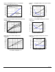
Figure 14. Normalization factor for non-saturated
and saturated CTR T
A
=85°C versus if
Figure 15. Collector-emitter current versus temperature
and LED current
Figure 16. Collector-emitter leakage versus
temperature
.1 1 10 100
0.0
0.5
1.0
1.5
2.0
Normalized to:
Vce = 10V, IF = 5mA, Ta = 25°C
Ta = 100°C
CTRce(sat) Vce = 0.4V
CTRNF - Normalized CTR Factor
IF - LED Current - mA
NCTRce(sat)
NCTRce
Ta=100°C
6050403020100
0
5
10
15
20
25
30
35
50°C
70°C
85°C
IF - LED Current - mA
Ice - Collector Current - mA
25°C
100806040200-20
10
10
10
10
10
10
10
10
-2
-1
0
1
2
3
4
5
Ta - Ambient Temperature - °C
Iceo - Collector-Emitter - nA
TYPICAL
Vce = 10V
Figure 17. -1 Propagation delay versus collector load re-
sistor
Figure 18. -2, -3 Propagation delay versus collector
load resistor
Figure 19. -4 Propagation delay versus collector
load resistor
.1 1 10 100
1
10
100
1000
1.0
1.5
2.0
2.5
3.0
3.5
4.0
RL - Load Resistor - KΩ
tPLH - Propagation Low-High - µs
tPHL - Propagation High-Low - µs
tPLH
tP H L
Ta = 25°C, IF = 10mA
Vcc = 5V, Vth = 1.5V
.1 1 10 100
1
10
100
1000
1.0
1.5
2.0
2.5
RL - Collector Load Resistor - KΩ
tPLH - Propagation Low-High - µs
tPHL - Propagation High-Low - µs
tPLH
tPHL
Ta = 25°C, IF = 10mA
Vcc = 5V, Vth = 1.5V
.1 1 10 100
1
10
100
1000
1.0
1.5
2.0
2.5
RL - Collector Load Resistor - KΩ
tPLH - Propagation Low-High - µs
tPHL - Propagation High-Low - µs
tPLH
tPHL
Ta = 25°C, IF = 10mA
Vcc = 5V, Vth = 1.5V