
Datasheet


www.vishay.com
6
Document Number 83621
Rev. 1.5, 26-Oct-04
IL30/ 31/ 55/ ILD30/ 31/ 55/ ILQ30/ 31/ 55
Vishay Semiconductors
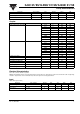
Figure 5. HFE Current Gain vs. Base Current
Figure 6. Low to High Propagation Delay vs. Collector Load
Resistance and LED Current
Figure 7. High to low Propagation Delay vs. Collector Load
Resistance and LED Current
iil30_05
V
CE
=1 V
V
CE
=5 V
.01 .1 1 10 100
12000
10000
8000
6000
4000
2000
0
Base Current
Hfe - Current Gain
iil30_06
0 5 10 15 20
0
20
40
60
80
Vcc=5V
Vth = 1.5 V
220 Ω
ıˇ
470 Ω
IF - LED Current - mA
tpLH - Low/High Propagation
Delay - µS
100 Ω
1.0 kΩ
iil30_07
0 5 10 15 20
0
5
10
15
20
100Ω
1kΩ
IF - LED Current - mA
tpHL - High/Low Propagation
delay - µs
Vcc = 5 V
Vth = 1.5 V
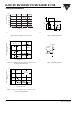
Figure 8. Switching Waveform
Figure 9. Switching Schematic
iil30_08
I
F
t
R
V
O
t
D
t
S
t
F
t
PHL
t
PLH
V
TH
=1.5 V
iil30_09
V
O
R
L
V
CC
=13.5 V
I
F
=50 mA
F=10 KHz,
DF=50%