
Datasheet


VISHAY
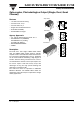
IL30/ 31/ 55/ ILD30/ 31/ 55/ ILQ30/ 31/ 55
Document Number 83621
Rev. 1.4, 20-Apr-04
Vishay Semiconductors
www.vishay.com
5
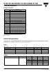
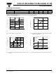
Switching Characteristics
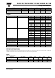
Typical Characteristics (T
amb
= 25 °C unless otherwise specified)
Parameter Test condition Symbol Min Typ. Max Unit
Rise time V
CC
= 13.5 V, I
F
= 50 mA, R
L
= 100 Ω t
r
10 µs
Fall time V
CC
= 13.5 V, I
F
= 50 mA, R
L
= 100 Ω t
f
35 µs
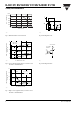
Fig. 1 Forward Voltage vs. Forward Current
Fig. 2 Normalized Non-Saturated and Saturated CTR
CE
vs. LED
Current
iil30_01
IF - Forward Current - mA
100101.1
0.7
0.8
0.9
1.0
1.1
1.2
1.
3
1.4
VF - Forward Voltage - V
Ta = –55°C
Ta = 25°C
Ta = 85°C
iil30_02
.1 1 10 100 1000
0.0
0.2
0.4
0.6
0.8
1.0
1.2
Vce =1V
Vce=5V
IF - LED Current - mA
NCTRce - Normalized CTRce
Vce=5V
IF=10mA
Normalized to:
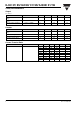
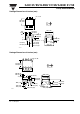
Fig. 3 Normalized Non-Saturated and Saturated Collector-Emitter
Current vs. LED Current
Fig. 4 Normalized Collector-Base Photocurrent vs. LED Current
iil30_03
100
1.1
.001
.01
.1
1
10
Vce=1V
Vce=5V
IF - LED Current - mA
NIce - Normalized Ice
IF = 10 mA
Vce=5V
Normalized to:
10
iil30_04
.1 1 10 100
.001
.01
.1
1
10
IF - LED Current - mA
NIcb - Normalized Icb
Vcb = 3.5 V
IF = 10 mA
Normalized to: