
Datasheet


VISHAY
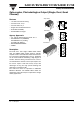
IL30/ 31/ 55/ ILD30/ 31/ 55/ ILQ30/ 31/ 55
Document Number 83621
Rev. 1.4, 20-Apr-04
Vishay Semiconductors
www.vishay.com
3
Coupler
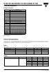
Electrical Characteristics
T
amb
= 25 °C, unless otherwise specified
Minimum and maximum values are testing requirements. Typical values are characteristics of the device and are the result of engineering
evaluation. Typical values are for information only and are not part of the testing requirements.
Input
GaAs emitter (per channel)
Collector (load) current I
C
125 mA
Power dissipation P
diss
150 mW
Derate linearly from 25 °C 2.0 mW/°C
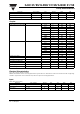
Parameter Test condition Part Symbol Value Unit
Total package power dissipation IL30 P
tot
250 mW
IL31 P
tot
250 mW
IL55 P
tot
250 mW
ILD30 P
tot
400 mW
ILD31 P
tot
400 mW
ILD55 P
tot
400 mW
ILQ30 P
tot
500 mW
ILQ31 P
tot
500 mW
ILQ55 P
tot
500 mW
Derate linearly from 25 °C IL30 3.3 mW/°C
IL31 3.3 mW/°C
IL55 3.3 mW/°C
ILD30 5.33 mW/°C
ILD31 5.33 mW/°C
ILD55 5.33 mW/°C
ILQ30 6.67 mW/°C
ILQ31 6.67 mW/°C
ILQ55 6.67 mW/°C
Isolation test voltage V
ISO
5300 V
RMS
Creepage ≥ 7.0 mm
Clearance ≥ 7.0 mm
Comparative tracking index 175
Storage temperature T
stg
- 55 to + 125 °C
Operating temperature T
amb
- 55 to + 100 °C
Lead soldering time at 260 °C 10 sec.
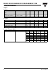
Parameter Test condition Symbol Min Typ. Max Unit
Forward voltage I
F
= 20 mA V
F
1.25 1.5 V
Reverse current V
R
= 3.0 V I
R
0.1 10 µA
Capacitance V
R
= 0 V C
O
25 pF
Parameter Test condition Part Symbol Value Unit