
Datasheet


Document Number: 83648 For technical questions, contact: optocoupler.answers@vishay.com
www.vishay.com
Rev. 1.6, 20-Apr-07 3
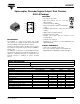
ILD223T
Optocoupler, Photodarlington Output,
Dual Channel,
SOIC-8 Package
Vishay Semiconductors
Note
As per IEC 60747-5-2, §7.4.3.8.1, this optocoupler is suitable for “safe electrical insulation” only within the safety ratings. Compliance with the
safety ratings shall be ensured by means of prodective circuits.
TYPICAL CHARACTERISTICS
T
amb
= 25 °C, unless otherwise specified
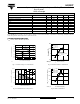
Fig. 3 - Forward Voltage vs. Forward Current
Fig. 4 - Peak LED Current vs. Duty Factor, τ
Fig. 5 - Normalized CTR
CE
vs. LED Current
Fig. 6 - CTR vs. LED Current
SAFETY AND INSULATION RATINGS
PARAMETER TEST CONDITION SYMBOL MIN. TYP. MAX. UNIT
Climatic classification (according to IEC 68 part 1) 55/100/21
Comparative tracking index CTI 175 399
V
IOTM
6000 V
V
IORM
560 V
P
SO
350 mW
I
SI
150 mA
T
SI
165 °C
Creepage distance 4mm
Clearance distance 4mm
Insulation thickness, reinforced rated per IEC 60950 2.10.5.1 0.2 mm
iild223t_01
100101
.1
0.7
0.8
0.9
1.0
1.1
1.2
1.3
1.4
I
F
- Forward Current (mA)
V
F
- Forward Voltage (V)
T
A
= - 55 °C
T
A
= 100 °C
T
A
= 25 °C
iild223t_02
10
-6
10
-5
10
-4
10
-3
10
-2
10
-1
10
0
10
1
10
100
1000
10000
t - LED Pulse Duration (s)
If(pk) - Peak LED Current (mA)
0.005
0.05
0.02
0.01
0.1
0.2
0.5
Duty Factor
t
τ
DF = /t
τ
100
0.1 1 10 100
iild223t_03
10
1
0.1
Normalized CTR
ce
Ta = - 20 °C
Ta = 25 °C
Ta = 50 °C
Ta = 70 °C
Normalized to:
If = 1 mA, V
CE
= 5 V
Ta = 25 °C
100
0.1 1 10 100
iild223t_03
10
1
0.1
Normalized CT
T
amb
= - 20 °C
T
amb
= 25 °C
T
amb
= 50 °C
T
amb
= 70 °C
Normalized to:
I
F
= 1 mA, V
CE
= 5 V
T
amb
= 25 °C
I
F
- LED Current (mA)
2000
0.1 1 10 10
0
iild223t_04
1500
1000
500
0
CTR
ce
- Current Transfer Ratio (%)
T
amb
= - 20 °C
T
amb
= 25 °C
T
amb
= 50 °C
T
amb
= 70 °C
V
CE
= 5 V
I
F
- LED Current (mA)