
Datasheet


HFA08TB60S
Bulletin PD-20607 rev. B 11/00
5
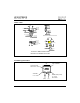
4. Q
rr
- Area under curve defined by t
rr
and I
RRM
t
rr
X I
RRM
Q
rr
=
2
5. di
(rec)M
/dt - Peak rate of change of
current during t
b
portion of t
rr
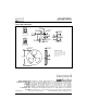
Fig. 10 - Reverse Recovery Waveform and
Definitions
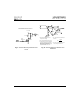
Fig. 9 - Reverse Recovery Parameter Test
Circuit
t
a
t
b
t
rr
Q
rr
I
F
I
RRM
I
RRM
0.5
di(rec)M/dt
0.75
I
RRM
5
4
3
2
0
1
di /dt
f
1. di
f
/dt - Rate of change of current
through zero crossing
2. I
RRM
- Peak reverse recovery current
3. trr - Reverse recovery time measured
from zero crossing point of negative
going I
F
to point where a line passing
through 0.75 I
RRM
and 0.50 I
RRM
extrapolated to zero current
REVERSE RECOVERY CIRCUIT
IRFP250
D.U.T.
L = 70µH
V = 200V
R
0.01
Ω
G
D
S
dif/dt
ADJUST