
Datasheet

ESH1PB, ESH1PC, ESH1PD
www.vishay.com
Vishay General Semiconductor
Revision: 19-Feb-15
3
Document Number: 88895
For technical questions within your region: DiodesAmericas@vishay.com
, DiodesAsia@vishay.com, DiodesEurope@vishay.com
THIS DOCUMENT IS SUBJECT TO CHANGE WITHOUT NOTICE. THE PRODUCTS DESCRIBED HEREIN AND THIS DOCUMENT
ARE SUBJECT TO SPECIFIC DISCLAIMERS, SET FORTH AT www.vishay.com/doc?91000
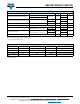
RATINGS AND CHARACTERISTICS CURVES (T
A
= 25 °C unless otherwise noted)
Fig. 1 - Forward Current Derating Curve
Fig. 2 - Maximum Non-Repetitive Peak Forward Surge Current
Fig. 3 - Typical Instantaneous Forward Characteristics
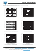
Fig. 4 - Typical Reverse Leakage Characteristics
Fig. 5 - Typical Junction Capacitance
Fig. 6 - Typical Transient Thermal Impedance
0
1.2
95 105 115 125 135 145 155 165
0.8
1.0
0.2
0.4
0.6
175
T
L
Measured
at the Cathode Band Terminal
Lead Temperature (°C)
Average Forward Rectified Current (A)
1
10
100
10
20
30
0
40
50
Number of Cycles at 50 Hz
Peak Forward Surge Current (A)
0.4 0.6 0.8 1.2 1.4
0.1
10
1
100
0.01
1.00.2 1.6
T
J
= 150 °C
T
J
= 125 °C
T
J
= 175 °C
T
J
= 25 °C
Instantaneous Forward Voltage (V)
Instantaneous Forward Current (A)
20 40 60 80 100
0.1
1
10
100
10 30 50 70 90
0.01
1000
T
J
= 150 °C
T
J
= 125 °C
T
J
= 175 °C
T
J
= 25 °C
Percent of Rated Peak Reverse Voltage (%)
Instantaneous Reverse Current (µA)
0.1 101 100
1
100
10
1000
Reverse Voltage (V)
Junction Capacitance (pF)
0.01 101 100
1
10
100
0.1
1000
t - Pulse Duration (s)
Transient Thermal Impedance (°C/W)