
Datasheet

BYV27-50, BYV27-100, BYV27-150, BYV27-200
www.vishay.com
Vishay Semiconductors
Rev. 1.8, 04-Sep-12
3
Document Number: 86042
For technical questions within your region: DiodesAmericas@vishay.com
, DiodesAsia@vishay.com, DiodesEurope@vishay.com
THIS DOCUMENT IS SUBJECT TO CHANGE WITHOUT NOTICE. THE PRODUCTS DESCRIBED HEREIN AND THIS DOCUMENT
ARE SUBJECT TO SPECIFIC DISCLAIMERS, SET FORTH AT www.vishay.com/doc?91000
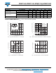
Fig. 5 - Max. Reverse Power Dissipation vs. Junction Temperature Fig. 6 - Diode Capacitance vs. Reverse Voltage
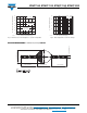
PACKAGE DIMENSIONS in millimeters (inches): SOD-57
0
10
20
30
40
50
60
70
25 50 75 100 125 150 175
16385
P
R
- Reverse Power Dissipation (mW)
T
j
- Junction Temperature (°C)
V
R
= V
RRM
P
R
- Limit
at 100 % V
R
P
R
- Limit
at 80 % V
R
0
20
40
60
80
100
0.1 1 10 100
V
R
- Reverse Voltage (V)
16386
C
D
- Diode Capacitance (pF)
f = 1 MHz
20543
3.6 (0.142) max.
26 (1.024) min.
4 (0.157) max.
26 (1.024) min.
0.82 (0.032) max.