
Datasheet

BYM10-xxx, GL41x
www.vishay.com
Vishay General Semiconductor
Revision: 11-Dec-13
4
Document Number: 88546
For technical questions within your region: DiodesAmericas@vishay.com
, DiodesAsia@vishay.com, DiodesEurope@vishay.com
THIS DOCUMENT IS SUBJECT TO CHANGE WITHOUT NOTICE. THE PRODUCTS DESCRIBED HEREIN AND THIS DOCUMENT
ARE SUBJECT TO SPECIFIC DISCLAIMERS, SET FORTH AT www.vishay.com/doc?91000
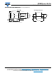
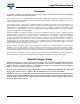
PACKAGE OUTLINE DIMENSIONS in inches (millimeters)
DO-213AB
1
st
band denotes type and positive end (cathode)
1
st
Band
Solderable Ends
D2 = D1
+ 0
- 0.008 (0.20)
D2
0.105 (2.67)
0.095 (2.41)
D1 =
0.022 (0.56)
0.018 (0.46)
0.022 (0.56)
0.018 (0.46)
0.205 (5.2)
0.185 (4.7)
Mounting Pad Layout
0.138 (3.5) MAX.
0.049 (1.25) MIN.
0.238 (6.0) REF.
0.118 (3.0) MIN.