
Datasheet


BYG10x-E3/HE3
www.vishay.com
Vishay General Semiconductor
Revision: 20-May-14
3
Document Number: 88957
For technical questions within your region: DiodesAmericas@vishay.com
, DiodesAsia@vishay.com, DiodesEurope@vishay.com
THIS DOCUMENT IS SUBJECT TO CHANGE WITHOUT NOTICE. THE PRODUCTS DESCRIBED HEREIN AND THIS DOCUMENT
ARE SUBJECT TO SPECIFIC DISCLAIMERS, SET FORTH AT www.vishay.com/doc?91000
Fig. 3 - Reverse Current vs. Junction Temperature
Fig. 4 - Max. Reverse Power Dissipation vs. Junction Temperature
Fig. 5 - Diode Capacitance vs. Reverse Voltage
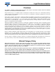
Fig. 6 - Reverse Recovery Time vs. Forward Current
Fig. 7 - Reverse Recovery Charge vs. Forward Current
1
10
100
1000
25 50 75 100 125 150
Reverse Current (µA)
Junction Temperature (°C)
V
R
= V
RRM
0
50
100
150
200
250
300
350
400
25 50 75 100 125 150
V
R
= V
RRM
P
R
- Limit at 100 % V
R
Reverse Power Dissipation (mW)
Junction Temperature (°C)
P
R
- Limit at 80 % V
R
0
5
10
15
20
25
30
0.1 1 10 100
f = 1 MHz
Reverse Voltage (V)
Diode Capacitance (pF)
0
0
1000
2000
3000
4000
5000
0.2 0.4 0.6 0.8
Reverse Recovery Time (ns)
Forward Current (A)
1.0
T
A
= 100 °C
T
A
= 125 °C
T
A
= 25 °C
T
A
= 75 °C
T
A
= 50 °C
I
R
= 0.5 A, i
R
= 0.125 A
0
0
400
800
1200
1600
2000
0.2 0.4 0.6 0.8
Reverse Recovery Charge (nC)
Forward Current (A)
1.0
T
A
= 100 °C
T
A
= 125 °C
T
A
= 25 °C
T
A
= 75 °C
T
A
= 50 °C
I
R
= 0.5 A, i
R
= 0.125 A