
Datasheet

www.vishay.com For technical questions within your region, please contact one of the following: Document Number: 88838
2 DiodesAmericas@vishay.com
, DiodesAsia@vishay.com, DiodesEurope@vishay.com Revision: 04-Nov-09
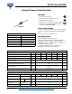
BY251P thru BY255P
Vishay General Semiconductor
Note
(1)
Thermal resistance from junction to ambient and from junction to lead at 0.375" (9.5 mm) lead length, P.C.B. mounted
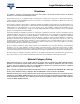
RATINGS AND CHARACTERISTICS CURVES
(T
A
= 25 °C unless otherwise noted)
Fig. 1 - Forward Current Derating Curve
Fig. 2 - Maximum Non-repetitive Peak Forward Surge Current
Fig. 3 - Maximum Non-repetitive Peak Forward Surge Current
Fig. 4 - Typical Instantaneous Forward Characteristics
THERMAL CHARACTERISTICS (T
A
= 25 °C unless otherwise noted)
PARAMETER SYMBOL BY251P BY252P BY253P BY254P BY255P UNIT
Typical thermal resistance
R
θJA
(1)
20
°C/W
R
θJL
(1)
10
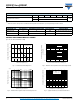
ORDERING INFORMATION (Example)
PREFERRED P/N UNIT WEIGHT (g) PREFERRED PACKAGE CODE BASE QUANTITY DELIVERY MODE
BY253P-E3/54 1.1 54 1400 13" diameter paper tape and reel
BY253P-E3/73 1.1 73 1000 Ammo pack packaging
4.0
3.0
2.0
1.0
0
0 25 50 75 100 125 150 175
Average Forward Rectied Current (A)
Ambient Temperature (°C)
60 Hz Resistive
or Inductive Load
10 mm Lead Length
1 10 100
1000
100
0
Number of Cycles at 60 Hz
Peak Forward Surge Current (A)
T
A
= 55 °C
8.3 ms Single Half Sine-Wave
0
20
40
60
80
100
0.01
0.1
1
10
Percent of Rated Peak Reverse Voltage (%)
Instantaneous Reverse Leakage
Current (μA)
T
J
= 125 °C
T
J
= 25 °C
T
J
= 75 °C
0.6
0.7
0.8
0.9
1.0
1.1
1.2
1.3
10
100
1
0.1
Instantaneous Forward Voltage (V)
Instantaneous Forward Current (A)
T
J
= 25 °C
Pulse Width = 300 μs
1 % Duty Cycle