
Datasheet

www.vishay.com
2
Document Number 85512
Rev. 1.5, 31-Mar-04
VISHAY
BAT81S / 82S / 83S
Vishay Semiconductors
Thermal Characteristics
T
amb
= 25 °C, unless otherwise specified
Electrical Characteristics
T
amb
= 25 °C, unless otherwise specified
Typical Characteristics (T
amb
= 25 °C unless otherwise specified)
Parameter Test condition Symbol Value Unit
Junction ambient l = 4 mm, T
L
= constant R
thJA
320 K/W
Junction temperature T
j
125 °C
Storage temperature range T
stg
- 65 to + 150 °C
Parameter Test condition Symbol Min Ty p. Max Unit
Forward voltage I
F
= 0.1 mA V
F
330 mV
I
F
= 1 mA V
F
410 mV
I
F
= 15 mA V
F
1V
Reverse current V
R
= V
Rmax
I
R
200 nA
Diode capacitance V
R
= 1 V, f = 1 MHz C
D
1.6 pF
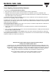
Fig. 1 Max. Reverse Power Dissipation vs. Junction Temperature
Fig. 2 Reverse Current vs. Junction Temperature
0
2
4
6
8
10
12
14
25 50 75 100 125 150
T
j
- Junction Temperature ( ° C)
15794
V
R
=60V
P - Reverse Power Dissipation ( mW )
R
R = 540 K/W
thJA
P
R
V
R
- Limit @ 100 %
P
R
V
R
- Limit @ 80 %
0.1
100
1000
25 50 75 100 125 150
1
10
15795
V
R
=V
RRM
ı
I - Reverse Current ( µA)
R
T
j
- Junction Temperature ( ° C)
Fig. 3 Forward Current vs. Forward Voltage
Fig. 4 Diode Capacitance vs. Reverse Voltage
0 0.5 1 1.5 2.0
I - Forward Current(A)
V
F
- Forward Voltage(V)
15796
F
T
j
=25°C
T
j
= 150 °C
0.1
1
10
100
1000
0.01
0
0.2
0.4
0.6
0.8
1.0
1.2
1.4
1.6
1.8
2.0
0.1 1 10 100
V
R
- Reverse Voltage(V)
15797
C - Diode Capacitance ( pF )
D
f=1MHz