
Datasheet


BAS385
www.vishay.com
Vishay Semiconductors
Rev. 2.1, 09-May-12
1
Document Number: 85504
For technical questions within your region: DiodesAmericas@vishay.com
, DiodesAsia@vishay.com, DiodesEurope@vishay.com
THIS DOCUMENT IS SUBJECT TO CHANGE WITHOUT NOTICE. THE PRODUCTS DESCRIBED HEREIN AND THIS DOCUMENT
ARE SUBJECT TO SPECIFIC DISCLAIMERS, SET FORTH AT www.vishay.com/doc?91000
Small Signal Schottky Diode
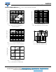
MECHANICAL DATA
Case: MicroMELF
Weight: approx. 12 mg
Cathode band color: black
Packaging codes/options:
TR3/10K per 13" reel (8 mm tape), 10K/box
TR/2.5K per 7" reel (8 mm tape), 12.5K/box
FEATURES
• Integrated protection ring against static
discharge
• Very low forward voltage
• AEC-Q101 qualified
• Material categorization:
For definitions of compliance please see
www.vishay.com/doc?99912
APPLICATIONS
• Applications where a very low forward voltage is required
PARTS TABLE
PART TYPE DIFFERENTATION ORDERING CODE INTERNAL CONSTRUCTION REMARKS
BAS385 V
R
= 30 V BAS385-TR3 or BAS385-TR Single diode Tape and reel
ABSOLUTE MAXIMUM RATINGS (T
amb
= 25 °C, unless otherwise specified)
PARAMETER TEST CONDITION SYMBOL VALUE UNIT
Reverse voltage V
R
30 V
Peak forward surge current t
p
= 10 ms I
FSM
5A
Repetitive peak forward current t
p
1 s I
FRM
300 mA
Forward continuous current I
F
200 mA
Average forward current V
RWM
= 25 V I
FAV
200 mA
THERMAL CHARACTERISTICS (T
amb
= 25 °C, unless otherwise specified)
PARAMETER TEST CONDITION SYMBOL VALUE UNIT
Junction to ambient air
On PC board
50 mm x 50 mm x 1.6 mm
R
thJA
320 K/W
Junction temperature T
j
125 °C
Storage temperature range T
stg
- 65 to + 150 °C
ELECTRICAL CHARACTERISTICS (T
amb
= 25 °C, unless otherwise specified)
PARAMETER TEST CONDITION SYMBOL MIN. TYP. MAX. UNIT
Forward voltage
I
F
= 0.1mA V
F
240 mV
I
F
= 1 mA V
F
320 mV
I
F
= 10 mA V
F
400 mV
I
F
= 30 mA V
F
500 mV
I
F
= 100 mA V
F
800 mV
Reserve current V
R
= 25 V, t
p
= 300 μs I
R
2.3 μA
Diode capacitance V
R
= 1 V, f = 1 MHz C
D
10 pF