
Datasheet


6TQ... Series
4
Bulletin PD-20283 rev. A 05/02
www.irf.com
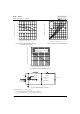
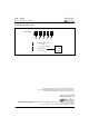
Fig. 8 - Unclamped Inductive Test Circuit
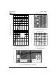
Fig. 5 - Maximum Allowable Case Temperature
Vs. Average Forward Current
Fig. 6 - Forward Power Loss Characteristics
Fig. 7 - Maximum Non-Repetitive Surge Current
FREE-WHEEL
DIO DE
40HFL40S02
CURRENT
MONITOR
HIGH-SPEED
SWITCH
IRFP460
L
DUT
Rg = 25 ohm
Vd = 25 Volt
+
(2) Formula used: T
C
= T
J
- (Pd + Pd
REV
) x R
thJC
;
Pd = Forward Power Loss = I
F(AV)
x V
FM
@ (I
F(AV)
/ D) (see Fig. 6);
Pd
REV
= Inverse Power Loss = V
R1
x I
R
(1 - D); I
R
@ V
R1
= 80% rated V
R
150
155
160
165
170
175
180
0123456789
DC
Allowable Case Temperature - ( C)
F(AV)
see note (2)
Square wave (D = 0.50)
80% Rated V applied
R
Average Forw ard Current - I (A)
0
1
2
3
4
5
0123456789
DC
Average Power Loss - (Watts)
F(AV)
RMS Limit
D = 0.20
D = 0.25
D = 0.33
D = 0.50
D = 0.75
Average Forw ard Current - I (A)
100
1000
10 100 1000 10000
FSM
p
Non-Repetitive Surge Current - I (A)
Square W ave Pulse Duration - t (m icrosec)
At Any Rated Load Condition
And W ith Rated V Applied
Following Surge
RRM