
Datasheet

5KP5.0A thru 5KP188A
www.vishay.com
Vishay General Semiconductor
Revision: 20-Nov-12
4
Document Number: 88308
For technical questions within your region: DiodesAmericas@vishay.com
, DiodesAsia@vishay.com, DiodesEurope@vishay.com
THIS DOCUMENT IS SUBJECT TO CHANGE WITHOUT NOTICE. THE PRODUCTS DESCRIBED HEREIN AND THIS DOCUMENT
ARE SUBJECT TO SPECIFIC DISCLAIMERS, SET FORTH AT www.vishay.com/doc?91000
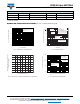
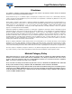
Fig. 5 - Power Derating Curve Fig. 6 - Maximum Non-Repetitive Forward Surge Current
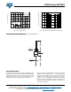
PACKAGE OUTLINE DIMENSIONS in inches (millimeters)
APPLICATION NOTES
The 5KP series of high power transient voltage suppressors
were designed to be used on the output of switching power
supplies. These devices may be used to replace crowbar
circuits. Both the 5 % and 10 % voltage tolerances are
referenced to the power supply output voltage level.
They are able to withstand high levels of peak current while
allowing a circuit breaker to trip or a fuse blow before
shorting. This will enable the user to reset the breaker or
replace the fuse and continue operation. For this type
operation, it is recommended that a sufficient mounting
surface be used for dissipating the heat generated by the
Transient Voltage Suppressor during the transient or
over-voltage condition.
L = 0.375" (9.5 mm)
Lead Lengths
P
D
- Power Dissipation (W)
T
L
- Lead Temperature (°C)
60 Hz
Resistive or
Inductive Load
8
6
4
2
0
0 25 50 75 100 125 150 175 200
1
10
100
200
300
400
500
450
350
250
8.3 ms Single Half Sine-Wave
Number of Cycles at 60 Hz
I
FSM
- Peak Forward Surge Current (A)
0.052 (1.32)
0.048 (1.22)
0.360 (9.1)
0.340 (8.6)
DIA.
1.0 (25.4)
MIN.
0.360 (9.1)
0.340 (8.6)
1.0 (25.4)
MIN.
P600