
Datasheet


www.vishay.com
6
Document Number 83717
Rev. 1.5, 27-Jan-05
4N35/ 4N36/ 4N37/ 4N38
Vishay Semiconductors
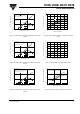
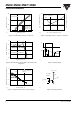
Figure 9. Normalized Photocurrent vs. I
F
and Temp.
Figure 10. Normalized Non-saturated HFE vs. Base Current and
Temperature
Figure 11. Normalized HFE vs. Base Current and Temp.
i4n25_09
0.
Normalized to:
0.01
1
1
10
I
F
- LED Current - mA
Normalized Photocurrent
.1 1 10 100
I
F
=10 mA, T
A
=25°C
Nib,
T
A
=–20°C
Nib,
T
A
= 25°C
Nib,
T
A
= 50°C
Nib,
T
A
= 70°C
i4n25_10
0.4
0.6
1.0
1.2
Normalized to:
Ib - Base Current - µA
1101001000
Ib=20 µA, Vce=10 V, T
A
=25°C
25°C
70°C
–20°C
NHFE - Normalized HFE
0.8
i4n25_11
0.0
0.5
1.0
1.5
25°C
–20°C
50°C
70°C
NHFE(sat) - Normalized Saturated HFE
1 10 100 1000
Vce=10 V, Ib=20 µA
T
A
=25°C
Vce=0.4 V
Ib - Base Current -
µA
Normalized to:
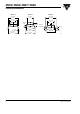
Figure 12. Propagation Delay vs. Collector Load Resistor
Figure 13. Switching Timing
Figure 14. Switching Schematic
i4n25_12
1
10
100
1000
RL - Collector Load Resistor - kΩ
t
PLH
- Propagation Delay - µs
2.5
2.0
1.5
1.0
.1 1 10 100
I
F
=10 mA,T
A
=25°C
V
CC
=5.0 V, Vth=1.5 V
t
PLH
t
PHL
t
PHL
- Propagation Delay - µs
i4n25_13
I
F
t
R
=1.5 V
V
O
t
D
t
S
t
F
t
PHL
t
PLH
V
TH
i4n25_14
V
CC
=5.0V
F=10 KHz,
DF=50 %
R
L
V
O
I
F
=1 0 mA