
Datasheet


Document Number: 93917 For technical questions, contact: diodes-tech@vishay.com
www.vishay.com
Revision: 21-Aug-08 1
Schottky Rectifier, 2 x 20 A
43CTQ...
Vishay High Power Products
FEATURES
• 175 °C T
J
operation
• Center tap configuration
• Low forward voltage drop
• High frequency operation
• Guard ring for enhanced ruggedness and long term
reliability
• High purity, high temperature epoxy encapsulation for
enhanced mechanical strength and moisture resistance
• Designed and qualified for industrial level
DESCRIPTION
This center tap Schottky rectifier series has been optimized
for low reverse leakage at high temperature. The proprietary
barrier technology allows for reliable operation up to 175 °C
junction temperature. Typical applications are in switching
power supplies, converters, freewheeling diodes, and
reverse battery protection.
PRODUCT SUMMARY
I
F(AV)
2 x 20 A
V
R
80/100 V
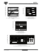
TO-220AB
Anode
13
2
Base
common
cathode
2
Common
cathode
Anode
MAJOR RATINGS AND CHARACTERISTICS
SYMBOL CHARACTERISTICS VALUES UNITS
I
F(AV)
Rectangular waveform 40 A
V
RRM
80/100 V
I
FSM
t
p
= 5 µs sine 850 A
V
F
20 Apk, T
J
= 125 °C (per leg) 0.67 V
T
J
Range - 55 to 175 °C
VOLTAGE RATINGS
PARAMETER SYMBOL 43CTQ080 43CTQ100 UNITS
Maximum DC reverse voltage V
R
80 100 V
Maximum working peak reverse voltage V
RWM
ABSOLUTE MAXIMUM RATINGS
PARAMETER SYMBOL TEST CONDITIONS VALUES UNITS
Maximum average
forward current
See fig. 5
per leg
I
F(AV)
50 % duty cycle at T
C
= 135 °C, rectangular waveform
20
A
per device 40
Maximum peak one cycle
non-repetitive surge current per leg
See fig. 7
I
FSM
5 µs sine or 3 µs rect. pulse
Following any rated
load condition and with
rated V
RRM
applied
850
A
10 ms sine or 6 ms rect. pulse 275
Non-repetitive avalanche energy per leg E
AS
T
J
= 25 °C, I
AS
= 0.50 A, L = 60 mH 7.50 mJ
Repetitive avalanche current per leg I
AR
Current decaying linearly to zero in 1 µs
Frequency limited by T
J
maximum V
A
= 1.5 x V
R
typical
0.50 A