
Datasheet


MB Series
5
Bulletin I2715 rev. I 03/03
www.irf.com
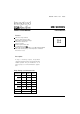
Fig. 6 - Current Ratings Characteristics
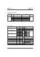
Fig. 7 - Forward Voltage Drop Characteristics
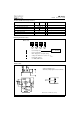
Fig. 3 - Total Power Loss Characteristics
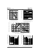
Fig. 9 - Maximum Non-Repetitive Surge Current
Fig. 10 - Maximum Non-Repetitive Surge Current
Average Forward Current (A)
Maximum Allowable Case temperature (°C)
Instantaneous Forward Voltage (V)
Instantaneous Forward Current (A)
Maximum Allowable Ambient Te
Average Forward Current (A)
Maximum Average Forward Power Loss (W)
Maximum Allowable Ambient Temperature (°C)
Number of Equal Amplitude Half Cycle Current Pulses (N)
Peak Half Sine Wave Forward Current (A)
Peak Half Sine Wave Forward Current (A)
Pulse Train Duration (s)
50
70
90
110
130
150
0 5 10 15 20 25 30 35 40
180˚
(Rect)
180˚
(Sine)
36MB..A Series
1
10
100
1000
0.5 1 1.5 2 2.5 3 3.5
Tj = 25˚C
Tj = 150˚C
36MB..A Series
0 25 50 75 100 125 150
1 K/W
2 K/W
3 K/W
4 K/W
5 K/W
7 K/W
RthSA = 0.7 K/W - Delta R
0
20
40
60
80
0 5 10 15 20 25 30
180˚
(Sine)
180˚
(Rect)
36MB..A Series
Tj = 150˚C
35
100
150
200
250
300
350
400
450
1 10 100
At Any Rated Load Condition And With
Rated Vrrm Applied Following Surge.
Initial Tj = 150˚C
@ 60 Hz 0.0083 s
@ 50 Hz 0.0100 s
36MB..A Series
100
150
200
250
300
350
400
450
500
0.01 0.1 1
Maximum Non Repetitive Surge Current
Versus Pulse Train Duration.
Initial Tj = 150˚C
No Voltage Reapplied
Rated Vrrm Reapplied
36MB..A Series