
Datasheet


MB Series
3
Bulletin I2715 rev. I 03/03
www.irf.com
T
J
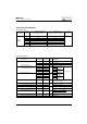
Junction temperature range - 55 to 150
o
C
T
stg
Storage temperature range - 55 to 150
o
C
R
thJC
Max. thermal resistance junction to case 1.7 1.2 K/W Per bridge
R
thCS
Max. thermal resistance, case to heatsink 0.2 K/W Mounting surface , smooth, flat and greased
wt Approximate weight 20 g
T Mounting Torque ± 10% 2.0 Nm Bridge to heatsink
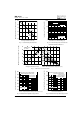
All dimensions in millimetres (inches)
Suggested plugging force:
200 N max; axially applied to faston terminals
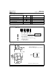
26 = 25A (Avg)
36 = 35A (Avg)
1 - Current rating code:
2 - Circuit configuration:
MB = Single phase european coding
3 - Voltage code: MB series = code x 10 = V
RRM
4 - Diode bridge rectifier:
A = 26MB, 36MB Series
36 MB 120 A
1
2
3
4
Thermal and Mechanical Specifications
Ordering Information Table
Outline Table
Device Code
Parameters 26MB-A 36MB-A Units Conditions
Not To Scale
0.8 (.03)
6.3 (.25)
10.5 (.41)
20.3 (.80)