
Datasheet


3
30EPF.. 30CPF.. QUIET
IR
Series
Bulletin I2118 rev. B 07/97
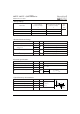
T
J
Max. Junction Temperature Range - 40 to 150 °C
T
stg
Max. Storage Temperature Range - 40 to 150 °C
R
thJC
Max. Thermal Resistance Junction 0.8 °C/W DC operation
to Case
R
thJA
Max. Thermal Resistance Junction 40 °C/W
to Ambient
R
thCS
Typical Thermal Resistance, Case to 0.2 °C/W Mounting surface , smooth and greased
Heatsink
wt Approximate Weight 6 (0.21) g (oz.)
T Mounting Torque Min. 6 (5)
Max. 12 (10)
Case Style TO-247AC JEDEC (Modified)
Thermal-Mechanical Specifications
Parameters 30.PF.. Units Conditions
Kg-cm
(Ibf-in)
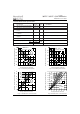
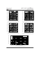
Fig. 3 - Forward Power Loss Characteristics Fig. 4 - Forward Power Loss Characteristics
0
5
10
15
20
25
30
35
0 5 10 15 20 25
RMS Limit
180°
120°
90°
60°
30°
Conduction Angle
Average Forward Current (A)
Maximum Average Forward Power Loss (W)
30EPF..
T = 150°C
J
0
5
10
15
20
25
30
35
40
45
0 5 10 15 20 25 30 35
DC
180°
120°
90°
60°
30°
RMS Limit
Conduction Period
Average Forward Current (A)
Maximum Average Forward Power Loss (W)
30EPF..
T = 150°C
J
90
100
110
120
130
140
150
0 5 10 15 20 25 30 35
30°
60°
90°
120°
180°
Maximum Allowable Case Temperature (°C)
Conduction Angle
Average Forward Current (A)
30EPF.. Series
R (DC) = 0.8 K/W
thJC
90
100
110
120
130
140
150
0 5 10 15 20 25 30 35 40 45 50
DC
30°
60°
90°
120°
180°
Maximum Allowable Case Temperature (°C)
Conduction Period
Average Forward Current (A)
30EPF.. Series
R (DC) = 0.8 K/W
thJC
Fig. 1 - Current Rating Characteristics Fig. 2 - Current Rating Characteristics