
Datasheet
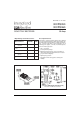


30CPQ050, 30CPQ060
PD-2.298 rev. A 12/97
3www.irf.com
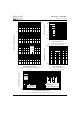
Fig. 2 - Typical Values Of Reverse Current
Vs. Reverse Voltage (Per Leg)
Fig. 3 - Typical Junction Capacitance
Vs. Reverse Voltage (Per Leg)
Fig. 4 - Max. Thermal Impedance Z
thJC
Characteristics (Per Leg)
Fig. 1 - Max. Forward Voltage Drop Characteristics
(Per Leg)
.001
.01
.1
1
10
10 0
1000
0 10203040506
0
R
R
125°C
100°C
75°C
50°C
25°C
Reverse Voltage - V (V)
Reverse Current - I (mA)
T = 150°C
J
100
10 00
0 5 1 0 15 20 25 30 3 5 40 45 50 55 6 0 6
5
T = 25°C
J
Reverse Voltage - V (V)
R
T
Junction Capacitance - C (pF)
.001
.01
.1
1
10
. 00001 .0001 .001 . 01 . 1 1 10 10
0
D = 0.33
D = 0.50
D = 0.25
D = 0.17
D = 0.08
1
thJC
t , Rectangular Pulse Duration (Seconds)
Ther mal Impedance - Z (°C/ W)
Single Pulse
(Thermal Resist ance)
2
t
1
t
P
DM
No tes :
1. Duty factor D = t / t
2. Peak T = P x Z + T
1
JDM
thJC C
2
.1
1
10
100
10 00
0.2.4.6.811.21.41.61.8
2
FM
F
Instantaneous Forward Current - I (A)
Forward Voltage Drop - V (V)
T = 150°C
T = 125°C
T = 25°C
J
J
J