
Datasheet


30BQ015
Bulletin PD-2.490 rev. I 07/04
4
www.irf.com
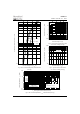
Fig. 4 - Maximum Average Forward Current
Vs. Allowable Lead Temperature
Fig. 5 - Maximum Average Forward Dissipation
Vs. Average Forward Current
Fig. 6 - Maximum Peak Surge Forward Current Vs. Pulse Duration
(2) Formula used: T
C
= T
J
- (Pd + Pd
REV
) x R
thJC
;
Pd = Forward Power Loss = I
F(AV)
x V
FM
@ (I
F(AV)
/ D) (see Fig. 6);
Pd
REV
= Inverse Power Loss = V
R1
x I
R
(1 - D); I
R
@ V
R1
= 80% rated V
R
Average Forward Current - I
F(AV)
(A)
Allowable Lead Temperature (°C)
Average Forward Current - I
F(AV)
(A)
Average Power Loss (Watts)
Square Wave Pulse Duration - T
p
(Microsec)
Non-Repetitive Surge Current - I
FSM
(A)
10
100
1000
10 100 1000 1000
0
At Any Rated Load Condition
And With Rated Vrrm Applied
Following Surge
50
60
70
80
90
100
110
012345
DC
D=0.20
D=0.25
D=0.33
D=0.50
D=0.75
Square wave (D=0.50)
80% Rated Vr applied
see note (2)
0
0.5
1
1.5
0 0.5 1 1.5 2 2.5 3 3.5 4 4.5
DC
RMS Limit
D = 0.20
D = 0.25
D = 0.33
D = 0.50
D = 0.75