
User`s guide
71
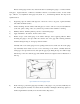
11) Protecting the gage: apply a protective coating over the entire gage and terminal area.
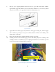
12) Measure the base resistance of the unstrained strain gage after its proper mounting but before
complete wiring. Check for surface contamination by measuring the isolation resistance between
the gauge grid and the stressed force detector specimen by means of an ohmmeter, if the
specimen is conductive. This should be done before connecting the lead wires to the
instrumentation.
13)
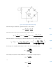
14) Strain gage will be connected to a Wheatstone bridge with quarter bridge set-up.
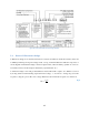
15) Connect the signal conditioner properly to provide power to the bridge and amplify the signal.
For set-up procedures, refer to Document 2.
16) Connect the inputs from the signal conditioner to the NI DAQ device with a BNC cable, use
channel AI0.
3.2.4 Construct the LabVIEW program
Refer to Document 3 for the tutorial to construct a basic VI program for this laboratory.
3.2.5 Verify the Set-up
Before starting the measurements, the strain gauge installations needs to be verified, the following steps
should be followed:
a. Run the VI program to monitor the readings.
b. Check for irrelevant induced voltages in the circuit by reading the voltage when the power supply
to the bridge is disconnected. Ensure that bridge output voltage readings for each strain-gage
channel are practically zero.
c. Connect the excitation power supply to the bridge and verify both the correct voltage level and its
stability.
d. Test out the strain gage bond by applying pressure to the gage. The reading should not be affected.
3.3 Taking Measurements
a. Before connecting the can, measure the can diameter. Record uncertainty. The middle part of the
can has the largest diameter, make sure to capture the diameter from the middle.