
User`s guide


121
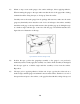
Figure 37 Lift tape
24) Apply adhesive and attach: apply a drop of adhesive to the gage’s bonding side, attach
the gauge and the surface by pressing on the tape for a minute. Wait two minutes before
making a firm wiping stroke over the tape.
25) Remove the tape and clean the terminals with alcohol and a cotton swab.
26) Soldering and stress relief: mask the gage grid area with drafting tape before soldering.
After soldering the wires to the terminals, tape the lead-in wires to the surface to prevent
the wires from being accidentally pulled from the tabs.
27) Measure the base resistance of the unstrained strain gage after its proper mounting but before
complete wiring. Check for surface contamination by measuring the isolation resistance between
the gauge grid and the stressed force detector specimen by means of an ohmmeter, if the
specimen is conductive. This should be done before connecting the lead wires to the
instrumentation.
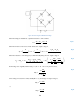
28) Strain gage should be connected to a Wheatstone bridge with quarter bridge set-up.
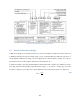
29) Connect the signal conditioner properly to provide power to the bridge and amplify the signal.
For set-up procedures, refer to Document 2.
30) Connect the inputs from the signal conditioner to the NI DAQ device with a BNC cable, use
channel AI0.
3.2.2 Construct the LabVIEW program
Refer to Document 3 for the tutorial to construct a basic VI program for this laboratory.