
Datasheet


www.vishay.com For technical questions, contact: diodestech@vishay.com
Document Number: 94157
4 Revision: 04-Mar-10
VS-20BQ030PbF
Vishay High Power Products
Schottky Rectifier, 2 A
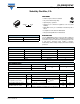
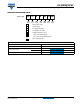
Fig. 5 - Maximum Average Forward Current vs.
Allowable Lead Temperature
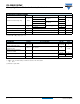
Fig. 6 - Maximum Average Forward Dissipation vs.
Average Forward Current
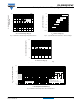
Fig. 7 - Maximum Peak Surge Forward Current vs. Pulse Duration
Note
(1)
Formula used: T
L
= T
J
- (Pd + Pd
REV
) x R
thJL
;
Pd = Forward power loss = I
F(AV)
x V
FM
at (I
F(AV)
/D) (see fig. 6);
Pd
REV
= Inverse power loss = V
R1
x I
R
(1 - D); I
R
at V
R1
= 80 % rated V
R
Lead Temperature (°C)
I
F(AV)
- Average Forward Current (A)
0 2.5 3.01.5
50
70
90
110
140
150
0.5 2.01.0
120
D = 0.20
D = 0.25
D = 0.33
D = 0.50
D = 0.75
DC
See note (1)
Square wave (D = 0.50)
80 % rated V
R
applied
60
80
100
130
0
Average Power Loss (W)
I
F(AV)
- Average Forward Current (A)
0
2.0 3.0
0.2
0.4
0.6
0.8
1.0
1.2
2.5
0.5
1.0 1.5
D = 0.20
D = 0.25
D = 0.33
D = 0.50
D = 0.75
RMS limit
DC
I
FSM
- Non-Repetitive Surge Current (A)
t
p
- Square Wave Pulse Duration (µs)
100
1000
10
100
1000
10 000
At any rated load condition
and with rated V applied
following surge
RRM
10