
Datasheet


16F(R) Series
5
Bulletin I20204 rev. A 09/98
www.irf.com
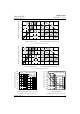
Fig. 3 - Forward Power Loss Characteristics
0 255075100
Maximum Allowable Ambient Temperature (°C)
1
0
K
/
W
1
5
K
/
W
R
=
4
K
/
W
-
D
e
l
t
a
R
t
h
S
A
6
K
/
W
8
K
/
W
2
0
K
/
W
3
0
K
/
W
0
4
8
12
16
20
0 4 8 12 16 20
Average Forward Current (A)
RMS Limit
Maximum Average Forward Power Loss (W)
Conduct ion Angle
180°
120°
90°
60°
30°
16F(R) Series
T = 175°C
J
Fig. 4 - Forward Power Loss Characteristics
0 25 50 75 100
Maximum Allowable Ambient Temperature (°C)
1
0
K
/
W
1
5
K
/
W
R
=
4
K
/
W
-
D
e
l
t
a
R
t
h
S
A
6
K
/
W
8
K
/
W
2
0
K
/
W
3
0
K
/
W
0
5
10
15
20
25
0 5 10 15 20 25 30
DC
180°
120°
90°
60°
30°
Average Forward Current (A)
RMS Limit
Maximum Average Forward Power Loss (W)
Conduct ion Period
16F(R) Series
T = 175°C
J
Fig. 5 - Maximum Non-Repetitive Surge Current Fig. 6 - Maximum Non-Repetitive Surge Current
125
150
175
200
225
250
275
300
325
110100
Peak Half Sine Wave Forward Current (A)
Number Of Equal Amplitude Half Cycle Current Pulses (N)
16F(R) Series
Initial T = 175°C
@ 60 Hz 0.0083 s
@ 50 Hz 0.0100 s
At Any Rated Load Condition And With
Rated V Applied Following Surge.
RRM
J
125
150
175
200
225
250
275
300
325
350
0.01 0.1 1
Peak Half Sine Wave Forward Current (A)
Pulse Train Duration (s)
Maximum Non Repetitive Surge Current
16F(R) Series
Initial T = 175°C
No Voltage Reapplied
Rated V Reapplied
RRM
Versus Pulse Train Duration.
J