
Datasheet


12TQ... Series
4
Bulletin PD-20239 rev. B 12/01
www.irf.com
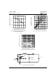
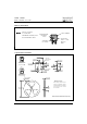
Fig. 8 - Unclamped Inductive Test Circuit
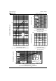
Fig. 5 - Maximum Allowable Case Temperature
Vs. Average Forward Current
Fig. 6 - Forward Power Loss Characteristics
Fig. 7 - Maximum Non-Repetitive Surge Current
0
2
4
6
8
10
12
0246810121416182022
DC
Average Power Loss - (Watts)
F( AV)
D = 0. 08
D = 0. 17
D = 0. 25
D = 0. 33
D = 0. 50
RMS Li mit
Average Forward Current - I (A)
115
125
135
145
155
0 4 8 12 16 20 24
DC
Allowable Case Temperat ure - (°C)
Average Forward Current - I (A)
F(AV)
12TQ
R (DC) = 2.0°C/W
thJC
100
1000
10 100 1000 10000
FSM
p
Non-Repetitive Surge Current - I (A)
At Any Rated Load Condition
And With Rated V Applied
Following Surge
RRM
Square Wave Pulse Duration - t (microsec)
FREE-WHEEL
D IO DE
40HFL40S02
CURRENT
MONITOR
HIGH-SPEED
SW ITCH
IRFP460
L
DUT
Rg = 25 ohm
Vd = 25 Volt
+