
Datasheet


12TQ... Series
2
Bulletin PD-20239 rev. B 12/01
www.irf.com
V
FM
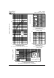
Max. Forward Voltage Drop (1) 0.56 V @ 15A
* See Fig. 1 0.71 V @ 30A
0.50 V @ 15A
0.64 V @ 30A
I
RM
Max. Reverse Leakage Current (1) 1.75 mA T
J
= 25 °C
* See Fig. 2 70 mA T
J
= 125 °C
C
T
Max. Junction Capacitance 900 pF V
R
= 5V
DC
, (test signal range 100Khz to 1Mhz) 25 °C
L
S
Typical Series Inductance 8.0 nH Measured lead to lead 5mm from package body
dv/dt Max. Voltage Rate of Change 10000 V/ µs
(Rated V
R
)
T
J
= 25 °C
T
J
= 125 °C
V
R
= rated V
R
Electrical Specifications
Parameters 12TQ Units Conditions
(1) Pulse Width < 300µs, Duty Cycle < 2%
T
J
Max. Junction Temperature Range -55 to 150 °C
T
stg
Max. Storage Temperature Range -55 to 150 °C
R
thJC
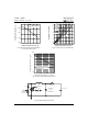
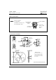
Max. Thermal Resistance Junction 2.0 °C/W DC operation * See Fig. 4
to Case
R
thCS
Typical Thermal Resistance, Case to 0.50 °C/W Mounting surface, smooth and greased
Heatsink
wt Approximate Weight 2 (0.07) g (oz.)
T Mounting Torque Min. 6 (5)
Max. 12 (10)
Thermal-Mechanical Specifications
Parameters 12TQ Units Conditions
I
F(AV)
Max. Average Forward Current 15 A 50% duty cycle @ T
C
= 120° C, rectangular wave form
* See Fig. 5
I
FSM
Max. Peak One Cycle Non-Repetitive 990 5µs Sine or 3µs Rect. pulse
Surge Current * See Fig. 7 250 10ms Sine or 6ms Rect. pulse
E
AS
Non-Repetitive Avalanche Energy 16 mJ T
J
= 25 °C, I
AS
= 2 .4 Amps, L = 5.5 mH
I
AR
Repetitive Avalanche Current 2.4 A Current decaying linearly to zero in 1 µsec
Frequency limited by T
J
max. V
A
= 1.5 x V
R
typical
Parameters 12TQ Units Conditions
Absolute Maximum Ratings
A
Following any rated
load condition and
with rated V
RRM
applied
Kg-cm
(Ibf-in)
Voltage Ratings
Part number 12TQ035 12TQ040 12TQ045
V
R
Max. DC Reverse Voltage (V)
V
RWM
Max. Working Peak Reverse Voltage (V)
35 40 45