
Datasheet


12F(R) Series
5
Bulletin I20205 rev. A 09/98
www.irf.com
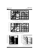
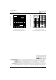
Fig. 3 - Forward Power Loss Characteristics
0 255075100
Maximum Allowable Ambient Temperature (°C)
R
=
8
K
/
W
-
D
e
l
t
a
R
t
h
S
A
6
K
/
W
1
0
K
/
W
1
2
K
/
W
1
5
K
/
W
2
0
K
/
W
3
0
K
/
W
0
2
4
6
8
10
12
14
02468101214
Average Forward Current (A)
RMS Limit
Maximum Average Forward Power Loss (W)
Conduction Angl e
180°
120°
90°
60°
30°
12F(R) Series
T = 175°C
J
Fig. 4 - Forward Power Loss Characteristics
0 255075100
Maximum Allowable Ambient Temperature (°C)
R
=
6
K
/
W
-
D
e
l
t
a
R
t
h
S
A
8
K
/
W
1
0
K
/
W
1
2
K
/
W
1
5
K
/
W
2
0
K
/
W
3
0
K
/
W
0
4
8
12
16
20
0 4 8 12 16 20
DC
180°
120°
90°
60°
30°
Average Forward Current (A)
RMS Limit
Maximum Average Forward Power Loss (W)
Conduction Period
12F(R) Series
T = 175°C
J
Fig. 5 - Maximum Non-Repetitive Surge Current Fig. 6 - Maximum Non-Repetitive Surge Current
10 0
12 5
15 0
17 5
20 0
22 5
25 0
1 10 100
Peak Half Sine Wave Forward Current (A)
Number Of Equal Amplitude Half Cycle Current Pulses (N)
12F(R) Series
Initial T = 175°C
@ 60 Hz 0.0083 s
@ 50 Hz 0.0100 s
J
At Any Rated Load Condition And With
Rated V Applied Following Surge.
RRM
100
125
150
175
200
225
250
275
0.01 0.1 1
Peak Hal f Sine Wave Forward Current (A)
Pulse Train Duration (s)
12F(R) Series
Initial T = 175°C
No Voltage Reapplied
Rated V Reapplied
RRM
J
Versus Pulse Train Duration.
Maximum Non Repetitive Surge Current