
Energy Guide
CMF Industrial
www.vishay.com
Vishay Dale
Revision: 16-Sep-16
3
Document Number: 31018
For technical questions, contact: ff2aresistors@vishay.com
THIS DOCUMENT IS SUBJECT TO CHANGE WITHOUT NOTICE. THE PRODUCTS DESCRIBED HEREIN AND THIS DOCUMENT
ARE SUBJECT TO SPECIFIC DISCLAIMERS, SET FORTH AT www.vishay.com/doc?91000
TEMPERATURE COEFFICIENT CODES
GLOBAL TC CODE HISTORICAL TC CODE TEMPERATURE COEFFICIENT
E T-9 25 ppm/°C
H T-2 50 ppm/°C
K T-1 100 ppm/°C
L T-0 150 ppm/°C
N T-00 200 ppm/°C
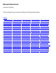
LOAD LIFE SHIFT DUE TO POWER AND DERATING (AT +70 °C AND AT +125 °C)
The power rating for the CMF parts is tied to the derating temperature, the heat rise of the parts, and the R for the load life performance.
When the tables/graphs below are used together they show that when the parts are run at their higher power ratings, the parts will run hotter,
which has the potential of causing the resistance of the parts to shift more over the life of the part.
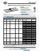
LOAD LIFE SHIFT VS. POWER RATING
LOAD LIFE
MAXIMUM R (TYPICAL TEST LOTS)
± 0.15 % ± 0.5 % ± 1.0 % ± 0.15 % ± 0.5 % ± 1.0 %
MODEL POWER RATING AT +70 °C POWER RATING AT +125 °C
CMF50 1/20 W and 1/10 W 1/8 W 1/4 W 1/20 W 1/10 W 1/8 W
CMF55, CMF07 1/10 W and 1/8 W 1/4 W 1/2 W 1/10 W 1/8 W 1/4 W
CMF60, CMF20 1/8 W and 1/4 W 1/2 W 3/4 W and 1 W 1/8 W 1/4 W 1/2 W
CMF65 1/4 W and 1/2 W 3/4 W 1 W and 1-1/2 W 1/4 W 1/2 W 3/4 W and 1 W
CMF70 1/4 W and 1/2 W 3/4 W 1 W and 1-3/4 W 1/4 W 1/2 W 3/4 W and 1-1/4 W
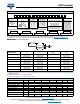
CMF resistors have an operating temperature range of -55 °C to +175 °C. They must be derated at high ambient temperatures according to
the derating curve.
Example:
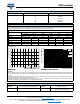
When a CMF55 part is run at 1/8 W in a 70 °C ambient environment, the resistor will generate enough heat that the surface temperature of
the part will reach about 19 °C over the ambient temperature, and over the life of the part this could cause the resistance value to shift up to
± 0.15 %.
If the same resistor was instead run at 1/4 W in a 70 °C environment, the element will heat up to about 30 °C over ambient, and over the life
of the part the resistance value could shift roughly ± 0.5 %.
And if the resistor was run at it maximum power rating of 1/2 W in a 70 °C environment, it will heat up to about 58 °C over ambient, and you
could see the resistance value shift roughly ± 1 % over the life of the part.
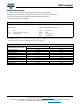
MATERIAL SPECIFICATIONS
Element Vacuum-deposited nickel-chrome alloy Coating
Flame retardant epoxy, formulated for superior
moisture protection
Core Fire-cleaned high purity ceramic Solderability
Continuous satisfactory coverage when tested
in accordance with MIL-R-10509
AMBIENT TEMPERATURE IN °C
DERATING
120
100
80
60
40
20
0
% NI REWOP DETAR
- 55
- 50
- 25
0
25 70 75 100 125
150
165
175
50 200
APPLIED POWER IN W
THERMAL RESISTANCE
120
100
80
60
40
20
0
HEAT RISE (°C ABOVE AMBIENT)
0 0.125 0.25 0.375 0.5 0.75 0.875
1
1.1250.625
CMF50
CMF55,
CMF07
CMF60,
CMF20
CMF65,
CMF70