
Energy Guide
CMF Industrial
www.vishay.com
Vishay Dale
Revision: 16-Sep-16
2
Document Number: 31018
For technical questions, contact: ff2aresistors@vishay.com
THIS DOCUMENT IS SUBJECT TO CHANGE WITHOUT NOTICE. THE PRODUCTS DESCRIBED HEREIN AND THIS DOCUMENT
ARE SUBJECT TO SPECIFIC DISCLAIMERS, SET FORTH AT www.vishay.com/doc?91000
Notes
• For additional information on packaging, refer to the Through-Hole Resistor Packaging document (www.vishay.com/doc?31544
).
(1)
Tolerances of ± 0.5 % (D), ± 0.25 % (C) and ± 0.1 % (B) are available only in 50 ppm and 25 ppm temperature coefficients.
Notes
(1)
Lead length for product in bulk pack. For product supplied in tape and reel, the actual lead length would be based on the body size, tape
spacing and lead trim.
(2)
Available with 0.032" (0.813 mm) lead [CMF60..95]
(3)
0.260" ± 0.020" (6.60 mm ± 0.51 mm) for values > 5 M
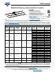
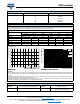
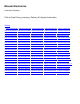
GLOBAL PART NUMBER INFORMATION
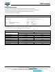
DIMENSIONS in inches (millimeters)
GLOBAL MODEL A B
C
(Max.)
D
CMF50
0.150 ± 0.020
(3.81 ± 0.51)
0.065 ± 0.015
(1.65 ± 0.38)
0.187 (4.75)
0.016 ± 0.002
(0.41 ± 0.05)
CMF55
0.240 ± 0.020
(3)
(6.10 ± 0.51)
0.090 ± 0.008
(2.29 ± 0.20)
0.290 (7.37)
0.025 ± 0.002
(0.64 ± 0.05)
CMF60
0.344 ± 0.031
(8.74 ± 0.79)
0.145 ± 0.015
(3.68 ± 0.38)
0.425 (10.80)
0.025 ± 0.002
(2)
(0.64 ± 0.05)
CMF65
0.562 ± 0.031
(14.27 ± 0.79)
0.180 ± 0.015
(4.57 ± 0.38)
0.687 (17.45)
0.025 ± 0.002
(0.64 ± 0.05)
CMF70
0.562 ± 0.031
(14.27 ± 0.79)
0.180 ± 0.015
(4.57 ± 0.38)
0.687 (17.45)
0.032 ± 0.002
(0.81 ± 0.05)
CMF07
0.240 ± 0.020
(6.10 ± 0.51)
0.090 ± 0.008
(2.29 ± 0.20)
0.290 (7.37)
0.025 ± 0.002
(0.64 ± 0.05)
CMF20
0.375 ± 0.040
(9.53 ± 1.02)
0.145 ± 0.015
(3.68 ± 0.38)
0.425 (10.80)
0.032 ± 0.002
(0.81 ± 0.05)
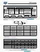
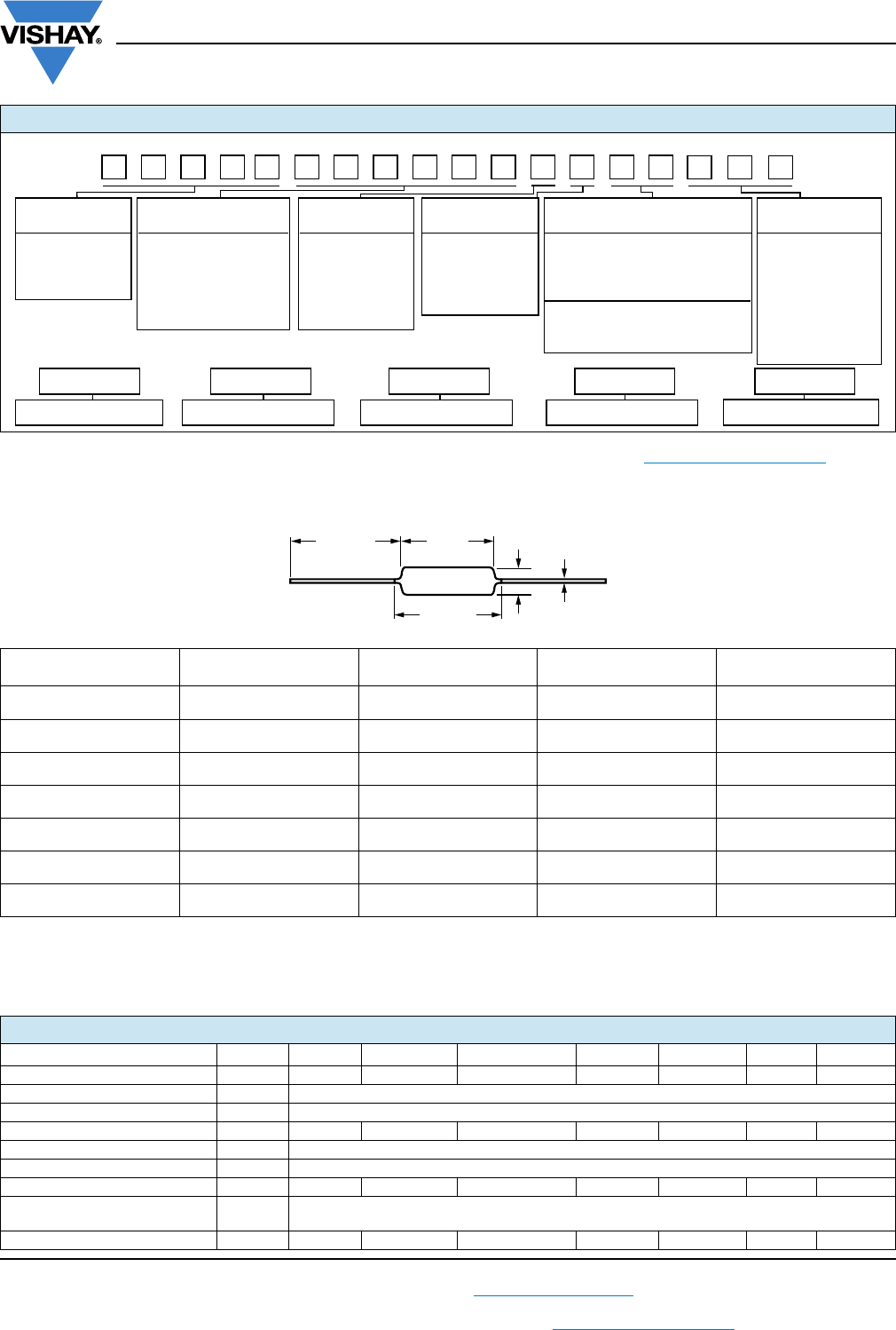
TECHNICAL SPECIFICATIONS
PARAMETER UNIT CMF50 CMF55 CMF07 CMF60 CMF20 CMF65 CMF70
Maximum Working Voltage V200 250 250 500 500 500 500
Insulation Voltage (1 Min) V
eff
> 500
Voltage Coefficient (Max.) ppm/V ± 5 (measured between 10 % and full rated voltage)
Dielectric Strength V
AC
450 450 450 750 750 900 900
Insulation Resistance 10
11
Operating Temperature Range °C -55 to +175
Terminal Strength (Pull Test) lb 2 2 5 2 5 2 5
Noise dB
0.10 μV/V over a decade of frequency, with low and intermediate resistance values typically
below 0.05 μV/V
Weight (Max.) g 0.12 0.28 0.28 0.50 0.60 1.00 1.10
GLOBAL MODEL RESISTANCE VALUE TOLERANCE PACKAGING
CODE
(See Standard R = Ω B = ± 0.1 % E = 25 ppm
EK = lead (Pb)-free, bulk
EA = lead (Pb)-free, T/R (full)
EB = lead (Pb)-free,
T/R (1000 pieces)
Electrical K = kΩ C = ± 0.25 % H = 50 ppm
Specifications M = MΩ D = ± 0.5 % K = 100 ppm
table) R10000 = 0.1 Ω F = ± 1 % L = 150 ppm
680K00 = 680 kΩ G = ± 2 % N = 200 ppm
1M0000 = 1.0 MΩ J = ± 5 %
New Global Part Numbering: CMF55301R00FKRE (preferred part numbering format)
CMF55301R00FKRE
Historical Part Number example: CMF-553010FT-1 (will continue to be accepted)
63R1-TF010355-FMC
HISTORICAL MODEL RESISTANCE VALUE TOLERANCE CODE TEMP. COEFFICIENT PACKAGING
Blank = standard
(Dash number)
(Up to 3 digits)
From
1 to 999
as applicable
70 = color banded,
5 bands (≤ 1 %)
80 = color banded,
4 bands (≥ 2 %)
88 = hot solder dip
SPECIAL
TEMPERATURE
COEFFICIENT
(1)
BF = tin/lead, bulk
RE = tin/lead, T/R (full)
R6 = tin/lead, T/R (1000 pieces)
B
D
C
(Max.)
1.500 ± 0.125
(1)
(38.10 ± 3.18)
A