USER MANUAL Virgo cutting manager (VIRGO CM)
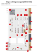
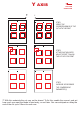
Virgo cutting manager (VIRGO CM) 9 3 20 2 4 21 22 2 5 1 8 23 17 13 12 6 18 15 14 11 10 19 7 16 USER INTERFACE
1. Cutting file preview. 2. Alignment adjustement controls. cutting direction -x move down the cutting file +x move up the cutting file -y move to the left the cutting file +y move to the right the cutting file 3. Status bar. 4. Selects the cutting file. 5. Open the last cutting file. 6. Controls to move the media forward or backward. 7. Camera preview . 8. To set the distance between the base of each black-mark. 9. To set the size of the black-marks. 10. Enable or disable blank mode. 11.
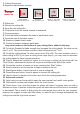
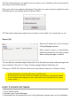
ADVANCED OPTIONS 24. Settings 24 25 25. List of cut logs 26 26. Set interface’s language 27 27. Restore of the plotter’s settings 28 28. Additional information Settings (24) 4 1 8 5 15 2 6 9 7 3 13 12 11 10 14 1. When you launch a cut with new offsets, they will be added to the deltas. The deltas store the saved offsets. 2. All the 100% magenta lines in your cutting file will be recognized as dashed. Here you can set the cut length and the spacing between each on of them.
4. Approximation of the cut curves. 5. . If cut sorting is enabled, the software will automatically select the order of the cut of all the shapes on the file. Otherwise, the cut will follow the .pdf layers order. 6. When you print your rolls, sometimes you may have distortion on your output. In that case, even with a correct set of the offsets, the cut may not match your print. You will have to enable the distortion fixer, and set the corrections.
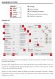
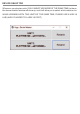
Y axis cutting direction + STEP 1 VERIFY THE CORRESPONDENCE OF THE CUT WITH THE PRINT STEP 2 AT THE POINT INDICATED, ADJUST OFFSET TO ALIGN THE CUT WITH THE PRINT STEP 3 INCREASE OR DECREASE THE “COMPRESSION” PARAMETER (Y) 7. With thin materials the cut may not be closed. To fix this, enable the overcut, and set how much you want the blade to start early, or end later. You can anticipate or delay the end of the cut up to 0.9mm for each one.
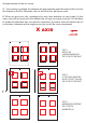
8. Check area parameters lets you change the position of the Black-Mark’s checking area, which is the blue square shown in the camera preview while the blank mode is disabled. 9. In case your print has distorted the output of your blackmark, you can change the tolerances to let the cam recognize it. The tolerances must be positive values. If your blackmark side is smaller than 4mm (for 4x4mm) or 2mm (for 2x2mm), you will have to reduce the minimum area by 100, until the blackmark is recognized.
14. This button allows you to set the current values in your interface as the new preset for any time you will load a new file. When you click it one window will appear. Through it you can choose to update the main interface preset, the settings preset or both of them 15. This button determines wheter the cut starts in the middle of a vertical side, or not. Report (25) Report will display the cuts run by the Cutting Manager system.
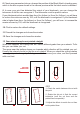
DEVICE SELECTOR Whenever you plug two units (YOU CANNOT USE MORE AT THE SAME TIME) to the pc, the device selector window will show up, and it will allow you to select which machine run. WHILE WORKING WITH TWO UNITS AT THE SAME TIME, PLEASE USE A USB 3.0 HUB (ALSO PLUGGED TO A USB 3.