Model 3100L Installation Guide © 2008 Directed Electronics Vista, CA N3100L 2008-12
table of contents What Is Included . . . . . . . . . . . . . . . . . . . . . . 2 Plug-In LED and Valet/Program Switch . . . . . . 17 Wiring Quick Reference Guide . . . . . . . . . . . . . 3 Internal Programming Jumper . . . . . . . . . . . . 18 Primary Harness (H1) Wire Connection Guide . . 4 On-Board Dual Stage Zone 2 Impact Sensor. . . 19 Door Lock Harness (H2) Wire Connection Guide . . 8 Type A Door Locks: Positive-Triggered, Relay Driven Systems . . . . . . . . . . . . . . . . .
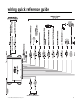
wiring quick reference guide © 2008 Directed Electronics Vista, CA 3
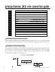
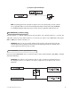
primary harness (H1) wire connection guide H1/1 H1/2 H1/3 H1/4 H1/5 H1/6 H1/7 H1/8 ______ ______ ______ ______ ______ ______ ______ ______ ORANGE (-) 500 mA GROUND-WHEN-ARMED OUTPUT WHITE (+/-) SELECTABLE LIGHT FLASH OUTPUT WHITE/BLUE BLACK/WHITE (-) 200 mA CHANNEL 3 VALIDITY OUTPUT (-) 200 mA INTERIOR LIGHT ILLUMINATION OUTPUT GREEN (-) DOOR TRIGGER INPUT, ZONE 3 BLUE (-) MULTIPLEX TRIGGER INPUT, ZONE 1 VIOLET (+) DOOR TRIGGER INPUT, ZONE 3 BLACK (-) CHASSIS GROUND INPUT H1/9 ______ YELLOW
(-) Negative Light Flash Output NOTE: For parking light circuits that draw 10 amps or more, the internal jumper must be switched to a (-) light flash output. (See the Internal Programming Jumper section of this guide.) P/N 8617 or a standard automotive SPDT relay must be used on the H1/2 light flash output harness wire. H1/3 WHITE/BLUE (-) channel 3 output This wire provides a (-) 200 mA output whenever the transmitter code controlling Channel 3 is received.
H1/5 GREEN (-) door trigger input, zone 3 Most vehicles use negative door trigger circuits. Connect the green wire to a wire which shows ground when any door is opened. In vehicles with factory delays on the domelight circuit, there is usually a wire that is unaffected by the delay circuitry. This wire will report Zone 3. H1/6 BLUE (-) multiplex trigger input, zone 1 This wire will respond to a negative input with an instant trigger. Inputs shorter than 0.
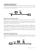
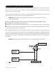
H1/8 BLACK (-) chassis ground connection Remove any paint and connect this wire to bare metal, preferably with a factory bolt rather than your own screw. (Screws tend to either strip or loosen with time.) We recommend grounding all your components, including the siren, to the same point in the vehicle. See the following diagram. H1/9 YELLOW (+) ignition input, zone 5 Connect this wire to an ignition source. This input must show (+)12V with the key in run position and during cranking.
H1/11 RED (+)12V constant power input Before connecting this wire, remove the supplied fuse. Connect to the positive battery terminal or the constant 12V supply to the ignition switch. NOTE: Always use a fuse within 12 inches of the point you obtain (+)12V power. Do not use the 15A fuse in the harness for this purpose. This fuse protects the module itself. H1/12 RED/WHITE channel 2, (-) 200mA output When the system receives the code controlling Channel 2, for longer than 1.
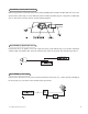
type A: positive (+) 12V pulses from the switch to the factory relays This security system can control Type A door locks directly, with no additional parts. The switch will have three wires on it, and one will test (+)12V constantly. The others will alternately pulse (+)12V when the switch is pressed to the lock or unlock position.
type B: negative (-) pulses from the switch to the factory relays This system is common in many Toyota, Nissan, Honda, and Saturn models, as well as Fords with remote-controlled door lock/unlock (some other Fords also use Type B). The switch will have three wires on it, and one wire will test ground all the time. One wire will pulse (-) when the switch locks the doors, and the other wire will pulse (-) when the switch unlocks the doors. This type of system is difficult to mistake for any other type.
type C: reversing polarity Interfacing with a reversing polarity system requires either two relays or one 451M (not included). It is critical to identify the proper wires and locate the master switch to interface properly. Locate wires that show voltage on lock and unlock. Cut one of the suspect wires and check operation of the locks from both switches. If one switch loses operation in both directions and the other switch operates in one direction only, you have located one of the target wires.
type D: after-market actuators In order for this system to control one or more after-market actuators, a 451M or two relays (optional) are needed. Vehicles without factory power door locks require the installation of one actuator per door. This requires mounting the door lock actuator inside the door. Other vehicles may only require one actuator installed in the driver's door if all door locks are operated when the driver's lock is used. The fuse used on 12-volt inputs should be 7.
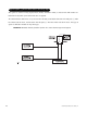
type E: mercedes-benz and audi (Certain years only) Door locks are controlled by an electrically activated vacuum pump. Some Mercedes and Audi models use a Type D system. Test by locking doors from the passenger key cylinder. If all the doors lock, the vehicle's door lock system can be controlled with just two relays (optional). The control wire can be found in either kick panel and will show (+)12V when doors are unlocked and (-) ground when doors are locked. To interface, see diagram below.
type F: one-wire system This system usually requires a negative pulse to unlock, and cutting the wire to lock the door. In some vehicles, these are reversed. It is found in some Nissan Sentras, some Nissan 240SX, and Nissan some 300ZX. It is also found in some Mazda MPV's and some Mitsubishi's.
type G: positive (+) multiplex This system is most commonly found in Ford, Mazda, Chrysler and GM vehicles. The door lock switch or door key cylinder may contain either one or two resistors. When interfacing with this type of door lock system, two relays or a 451M must be used. single-resistor type If one resistor is used in the door lock switch/key cylinder, the wire will pulse (+)12V in one direction and less than (+)12V when operated in the opposite direction.
type H: negative (-) multiplex The system is most commonly found in Ford, Mazda, Chrysler and GM vehicles. The door lock switch or door key cylinder may contain either one or two resistors. When interfacing with this type of door lock system, two relays or a 451M must be used. single-resistor type If one resistor is used in the door lock switch/key cylinder, the wire will pulse ground in one direction and resistance to ground when operated in the opposite direction.
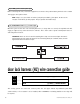
starter interrupt harness (H3) wire connection guide H3/1 H3/2 ______ ______ BLACK STARTER INTERRUPT INPUT BLACK STARTER INTERRUPT OUTPUT H3/1 and H3/2 BLACK starter interrupt wires Use one of these wire as a starter interrupt input and the other as a starter interrupt output wire NOTE: These two black wires are interchangeable. plug-in LED and valet/program switch The LED and the Valet/Program switch both plug into the control module.
internal programming jumper light flash jumper This jumper is used to determine the light flash output. In the (+) position, the on-board relay is enabled and the unit will output (+)12V on the H1/2 WHITE wire. In the (-) position, the on-board relay is disabled. The H1/2 WHITE wire will supply a (-) 200 mA output suitable for driving factory parking light relays. To access the jumper, open the control module.
on-board dual stage zone 2 impact sensor There is a dual-stage impact sensor inside the control unit. Adjustments are made via the rotary control as indicated above. Since the impact sensor does not work well when mounted firmly to metal, we recommend against screwing down the control module. We recommend mounting the control module to a large wiring loom. NOTE: When adjusting the sensor, it must be mounted in the same location where it will be after the installation is completed.
transmitter/receiver remote control code learning The system comes with two transmitters that have been taught to the receiver. Use the following transmitter/receiver remote control code learning to add transmitters to the system or to change button assignments if desired. The Valet®/Program button, plugged into the blue port, is used for programming. There is a basic sequence to remember whenever programming this unit: Door, Key, Choose, Transmit and Release. 1. Open a door.
4. Press the transmitter button. While HOLDING the Valet®/Program switch, press the transmitter button that you wish to assign to that channel. The unit will chirp indicating successful programming. You cannot teach a transmitter button to the system more than once. NOTE: For Channel 7, press Button I (see Transmitter Configuration section of this guide) to program the Auto-learn Standard Configuration on a three-button transmitter. 5. Release.
operating settings remote control code learning Many of the operating settings of this unit are programmable. They can be changed whenever necessary through Operating Settings Remote Control Code Learning. The Valet®/Program push-button switch, plugged into the blue port, is used together with a programmed transmitter to change the settings. The operating settings dictate how the unit operates. It is possible to access and change any of the feature settings using the Valet®/Program switch.
To access another feature: You can advance from feature to feature by pressing and releasing the Valet®/Program switch the number of times necessary to get from the feature you just programmed to the feature you wish to access. For example, if you just programmed Feature 1 and you want to program Feature 2: 1. Release the Valet®/Program switch. 2. Press and release the Valet/Program switch once to advance from Feature 1 to Feature 2. 3. Press the Valet®/Program switch once more and HOLD it. 4.
feature descriptions 1 ACTIVE/PASSIVE ARMING: When active arming is selected, the system will only arm when the transmitter is used. When set to passive, the system will arm automatically 30 seconds after the last door is closed. Passive arming is indicated by the rapid flashing of the LED when the last protected entry point is closed. 2 CONFIRMATION CHIRPS ON/OFF: This feature controls the chirps that confirm the arming and disarming of the system.
nuisance prevention circuitry™ NPC™ requires that you change the way you test the system, as NPC™ will bypass an input zone for 60 minutes. If the system “sees” the same zone trigger three times AND the triggers are spaced less than an hour apart, the system will bypass that input zone for 60 minutes. If that zone does not attempt to trigger the system during the 60-minute bypass period, the zone’s monitoring will begin again at the end of the hour.
troubleshooting ■ Door input does not immediately trigger full alarm. Instead, first I hear chirps for 3 seconds: That's how the progressive two-stage door input works! This is a feature of this system. This is an instant trigger, remember, since even if the door is instantly re-closed, the progression from chirps to constant siren will continue.