
RE_240-1CA20


Manual VIPA System 200V Chapter 3 Deployment
HB97E - CP - RE_240-1CA20 - Rev. 12/42 3-33
For every character frame there are 3 data formats available. The data
formats are different in the number of data bits, with or without parity bit and
number of stop bits.
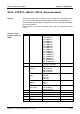
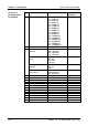
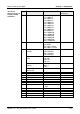
The transfer parameter byte has the following structure:
Byte Function Range Default parameter
2 Bit 1/0
Data bits
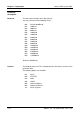
00b: 5 Data bits
01b: 6 Data bits
10b: 7 Data bits
11b: 8 Data bits
11b: 8 Data bits
Bit 3/2
Parity
00b: none
01b: odd
10b: even
11b: even
00b: none
Bit 5/4
Stop bits
01b: 1
10b: 1,5
11b: 2
01b: 1 Stop bit
Bit 7/6
Flow control
00b: none
01b: Hardware
10b: XON/XOFF
00b: none
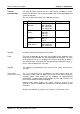
Number of data bits that represent a character.
The parity is depending on the value even or odd. For the purposes of the
parity check, the information bits are expanded by the parity bit. The value
of the parity bit ("0" or "1") completes the value of all the bits to obtain a
pre-arranged state. If the parity was not specified, the parity bit is set to "1"
but it is not included in the assessment.
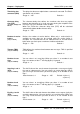
The stop bits are appended to each character and signify the end of the
character.
This is a mechanism that synchronizes the data transfer when the
transmitting station sends the data faster than it can be processed by the
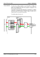
receiving station. Flow control can be hardware- or software-based
(XON/XOFF). Hardware flow control employs the RTS and CTS lines and
these must therefore be wired accordingly.
Software flow control employs the control characters XON=11h and
XOFF=13h. Please remember that your data must not contain these control
characters.
Default: 13h (data bits: 8, parity: none, stop bits: 1, flow control: none)
Transfer
parameter byte
Data bits
Parity
Stop bits
Flow control
(at ASCII and STX/ETX)