
RE_240-1CA20


Manual VIPA System 200V Chapter 3 Deployment
HB97E - CP - RE_240-1CA20 - Rev. 12/42 3-25
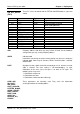
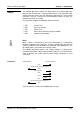
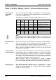
Sample input message
A
ctive partner Passive partner
Message header
Input
Flags
as of flag byte 16
32 flag bytes
coordination
flags MB 6.4
End of message
+ Block Check Char
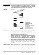
Reaction message
+ Data
MB16
MB17
.
.
.
.
.
.
MB47
End of message
+ Block Check Char
STX
DLE
00
00
E
M
00
10
00
20
06
04
DLE
ETX
BCC
DLE
STX
DLE
00
00
00
00
AB
CD
EF
00
01
02
.
.
FF
DLE
ETX
BCC
DLE
Byte
xx
Error code
3
00
00
Reaction
message
flag
0
1
200
Byte
00
00
Message
identifier
0
1
E
X
Input command
Data type
2
3
xx
xx
Parameter 1
Destination
4
5
yy
yy
Parameter 2
Quantity
6
7
zz
zz
Parameter 3
Coordinnation flag
8
9
aa
bb
Data
4
-
N
xy
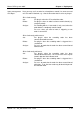
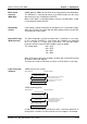
Normal message Reaction message
with N = 4 ... 127
When the data exceeds 128Byte, additional messages
will be sent.
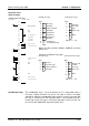
Structure of additional messages
Byte
xx
Error code
3
FF
00
Flag for next
reaction
message
0
1
2
00
Byte
FF
00
Flag for
next message
0
1
E
X
Input command
data type
2
3
aa
bb
Data
4
-
N
xy
Next message Next reaction message
with N = 4 ... 127
The coordination flag is set in the partner PLC in active-mode when a
message is being received. This occurs for input as well as for output
commands. When the coordination flag has been set and a message with
this flag is received, then the respective data is not accepted (or trans-
ferred) and a reject message is sent (error code 32h). In this case the user
has to reset the coordination flag in the partner PLC.
Structure of the
input message
Coordination flags