
RE_240-1CA20


Manual VIPA System 200V Chapter 2 Hardware description
HB97E - CP - RE_240-1CA20 - Rev. 12/42 2-5
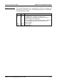
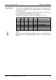
The communication processor is provided with 4 LEDs for the purpose of
displaying the operating status. The following table depicts the description
and the color of these LEDs.
Name Color Description
PW yellow Indicates that power is available
ER red For Modbus this signalizes an internal error
other protocols: error indicator for open circuit lines,
overflow, parity or framing errors.
The error LED is reset automatically after 4s. If diagnos-
tics are enabled the error causes transmission of
diagnostic bytes.
TxD green Transmit data
RxD green Receive data
LEDs