Fusion FPR-210+ Pedestal Fusion FPR-210+ Manual and Robotic Pedestal Operators Guide Part Nos. V3952-0005 www.vintenradamec.
Publication Part No. V3952-4987 Published by Vitec Videocom Ltd Supports Technical Publications Department Western Way, Bury St Edmunds Suffolk IP33 3TB United Kingdom Email: technical.publications@vitecgroup.com Copyright © 2014 All rights reserved. Original Instructions: English All rights reserved throughout the world.
Operators guide Contents Page Safety instructions . . . . . . . . . . . . . . . . . . . . . . . . . . . . . . . . . . . . . . . . . . . . . . . . . 2 Components and connectors . . . . . . . . . . . . . . . . . . . . . . . . . . . . . . . . . . . . . . . . 4 Introduction and description. . . . . . . . . . . . . . . . . . . . . . . . . . . . . . . . . . . . . . . . 10 Column. . . . . . . . . . . . . . . . . . . . . . . . . . . . . . . . . . . . . . . . . . . . . . . . . . . . . . . . . . . . . . . 10 Base. .
Fusion FPR-210+ pedestal Safety instructions Important information on the safe installation and operation of this product. Read this information before operating the product. For your personal safety, read these instructions. Do not operate the product if you do not understand how to use it safely. Save these instructions for future reference. Warning Symbols Used in these Instructions Safety cautions are included in these instructions.
Operators guide Mounting and Installation WARNING! Always ensure that all power and auxiliary communications cables are routed so that they do not present any danger to personnel. Take care when routing cables in areas where robotic equipment is in use. Water, Moisture and Dust WARNING! Protect the product from water, moisture and dust. The presence of electricity near water can be dangerous. Operating Environment CAUTION! The product should not be used outside the operating temperature limits.
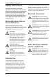
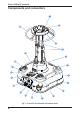
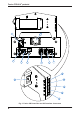
Fusion FPR-210+ pedestal Components and connectors 1 2 21 3 4 20 5 19 6 18 17 7 16 8 15 9 14 13 12 10 11 Fig.
Operators guide [1] . . . . . . . . . . . . . . . . . . . . . . . . . . . . . . . . . . . . . . . . . . . . . . . . . . . . . . . . . . . Pressure gauge [2] . . . . . . . . . . . . . . . . . . . . . . . . . . . . . . . . . . . . . . . . . . . . . . . . . . . . . . . .Head mounting plate [3] . . . . . . . . . . . . . . . . . . . . . . . . . . . . . . . . . . . . . . . . . . . . . . . . . . . . . Schrader valve and cap [4] . . . . . . . . . . . . . . . . . . . . . . . . . . . . . . . . . . . . . . . . . . .
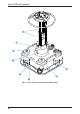
Fusion FPR-210+ pedestal 27 26 6 25 22 24 6 23 Fig.
Operators guide [22] . . . . . . . . . . . . . . . . . . . . . . . . . . . . . . . . . . . . . . . . . . . . . . Driven double-wheel sets (2 off) [23] . . . . . . . . . . . . . . . . . . . . . . . . . . . . . . . . . . . . . . . USB configuration port (with cover plug) [24] . . . . . . . . . . . . . . . . . . . . . . . . . . . . . . . . . . . . . . Servo configuration port (with cover plug) [25] . . . . . . . . . . . . . . . . . . . . . . . . . . . . . . . . . . . . . . . . . . .
Fusion FPR-210+ pedestal 36 37 41 38 39 40 Fig.
Operators guide [28] . . . . . . . . . . . . . . . . . . . . . . . . . . . . . . . . . . . . . . . . . . . . . . . . . . . . . Power ON/OFF switch [29] . . . . . . . . . . . . . . . . . . . . . . . . . . . . . . . . . . . . . . . . . . . . . . . . . . . . . . . . . . . . . Cable clamp [30] . . . . . . . . . . . . . . . . . . . . . . . . . . . . . . . . . . . . . . . . . . . . . . . . . . . . Ethernet port (auxiliary) [31] . . . . . . . . . . . . . . . . . . . . . . . . . . . . . . . . . . .
Fusion FPR-210+ pedestal Introduction and description This Operators Guide describes how to set up and operate the Fusion FPR-210+. The FPR-210+ pedestal has been designed for integration with the Fusion FH/R-145 pan and tilt heads and Vinten Radamec Control Systems (VRC) using the Intelligent Control Engineering (ICE) system. Each product within the Fusion FPR-210+ range of pedestals comprises a central two-stage, telescopic column mounted in a moveable base.
Operators guide Installation Unpacking WARNING! 130kg/286.6 lb LIFTING AID REQUIRED. Use a lifting hoist capable of safely lifting the product. WARNING! 1. DO NOT lift the pedestal by the steering ring—use the lifting handles on top of the pedestal base. 2. DO NOT release the column lock, if the pedestal pressure exceeds 4 bar (60 psi) without a balancing load mounted. Reduce pressure as necessary using the Schrader valve cap.
Fusion FPR-210+ pedestal Directly mounting a Fusion head to the pedestal WARNING! 1. DO NOT release the column lock, if the pedestal pressure exceeds 4 bar (60 psi) without a balancing load installed. Reduce as necessary, using the Schrader valve cap. 2. DO NOT lean over the pedestal. A pressurised pedestal could rise rapidly when the column lock is released. ALWAYS restrain the column by hand pressure on the pedestal base. 3.
Operators guide 6. Push down on the steering ring [21] against residual pressure and release the column lock [5]. Allow the column to extend under hand restraint. Mounting a Quickfix® adaptor In situations where heads are often interchanged on pedestals and tripods, it is recommended that a Vinten heavy-duty Quickfix adaptor (part no. 3490-3) is used. The adaptor provides an easier and quicker method of mounting and removing heads from a pedestal or tripod.
Fusion FPR-210+ pedestal Pressurising the pedestal WARNING! DO NOT pressurise the pedestal beyond the maximum safe working pressure indicated by the leading edge of the red sector on the gauge. CAUTION! This pedestal must be pressurised with nitrogen or clean, dry air only to prevent internal corrosion. CAUTION! Do not reduce pedestal pressure below 3.5 bar (50 psi). This ensures that the elevating mechanism remains in tension, preventing damage to the pedestal.
Operators guide Pressurising from an external pressure source WARNING! DO NOT exceed 4 bar (60 psi) without a balancing load installed. WARNING! DO NOT adjust the pressure relief valve. Personal injury and pedestal damage may occur. A pressure-reducing valve must be fitted between the gas cylinder and the outlet connection of the hose. The maximum pressure on the outlet side of the reducing valve must not exceed 18.
Fusion FPR-210+ pedestal 6. Disconnect the hose from the pedestal charging valve, and refit the Schrader valve cap [3]. Remove the pump. NOTE: The Schrader valve cap forms a primary pressure seal. Always replace the cap and secure. Electrical connections WARNING! It is recommended to use a residual current device (RCD) to protect personnel should the power cable become damaged. WARNING! 1. DO NOT plug moving devices into the auxiliary (Aux ) power port. 2.
Operators guide • The auxiliary (Aux) power output socket [32] is protected by a system fuse, but is permanently live and intended to power the ICE interface. Fig. 8 ICE Interface Power Connection USB configuration port The USB port [23] is located beneath a protective cover on the North side of the base. This port allows external connection to a pedestal configuration software tool.
Fusion FPR-210+ pedestal ICE Interface Ethernet Connections The following ICE Ethernet connections are made to the ICE interface. Control system ICE head Fig.
Operators guide Height control box installation If the optional accessory height control box (V3952-1910) is to be installed, proceed as follows: 1. Using the cable tie provided, install the height control box onto a pan bar or the pedestal steering ring (convenient location for the operator). Fig. 10 Height control box installation 2. Connect the supplied link cable to the height control box. Fig.
Fusion FPR-210+ pedestal 3. Connect the other end of the cable into the height control socket [17] near the side of the pedestal column Fig. 12 Pedestal height control socket Operation Parking brake CAUTION! Do not apply the brake while the pedestal is in motion. The pedestal may become unstable and the brake may be damaged. The pedestal base is provided with a parking brake [18] on one wheel. The brake is not designed to slow the pedestal while in motion (see Fig. 1).
Operators guide Cable guard CAUTION! Cable guards should be set to the minimum height possible, to prevent the pedestal damaging studio power and data cables. The height-adjustable cable guard is lowered by depressing the recessed cable guard buttons [12]. These buttons are located on the side of the base, near each wheel. When lowered, the cable guard can be raised in predefined increments as required (see Fig. 1). Using the column lock WARNING! 1.
Fusion FPR-210+ pedestal Height adjustment WARNING! 1. ALWAYS collapse the moving column and engage the column lock, when wheeling the pedestal across uneven/sloping surfaces between shots with the full payload fitted, to prevent loss of stability (toppling hazard!). 2. Take care not to trap fingers under the steering hub or between column elements while the pedestal height is being reduced. The column has an on-shot stroke of 770 mm (30 in.).
Operators guide Steering Directional manual control of the pedestal is achieved by turning the steering ring [21]. The steering system is geared, so that the skid wheels turn by the same amount as the steering ring. This ensures, for example, that when the pedestal is set to CRAB, turning the steering ring by 90° will also cause the pedestal to change direction by 90° (see Fig. 1). The pedestal has a changeover mechanism to switch between STEER and CRAB mode.
Fusion FPR-210+ pedestal To select manual pedestal movement/steering on the pedestal, rotate the steering mode knob [10] clockwise to the MAN position and rotate the steering ring [21] to re-engage the pedestal wheels. Movement indicators The movement indicators [25] will flash to warn when the pedestal moves across the floor. The indicators also flash when the camera unit is initialised by the control system, to confirm the correct unit has been selected.
Operators guide Bumper sensitivity at the control box/alignment sensor is factory set. Collision detection area Fig. 15 Collision Detection Area To adjust the bumper sensitivity, proceed as follows: 1. Ensure that the pedestal is fully prepared with the payload correctly fitted and balanced. Power up the pedestal. 2. Check the sensitivity of the bumper sensors by tapping the bumper lightly. The bumper manual reset [13] illuminates when the sensors have detected a collision. 3.
Fusion FPR-210+ pedestal Transportation and storage WARNING! 130kg/286.6 lb LIFTING AID REQUIRED. Use a lifting hoist capable of safely lifting the product. WARNING! DO NOT lift the pedestal by the steering ring—use the lifting handles only. CAUTION! Do not reduce pedestal pressure below 3.5 bar (50 psi). This ensures that the elevating mechanism remains in tension, preventing damage to the pedestal.
Operators guide Maintenance General This pedestal is robustly made to high engineering standards and little attention is required to maintain serviceability. Attention to the following points will ensure a long and useful service life with minimum need for repair. Routine checks During use, check the following: 1. Check the balance of the pedestal. Refer to the section Pressurising the pedestal on page 14 if rebalancing is required. 2. Check the data communication with the control panel.
Fusion FPR-210+ pedestal 1. Switch OFF power to the pedestal [34] and disconnect the power lead [32]. 2. Unscrew the four fixing screws [9.1] and lift off the panel [9] to expose the internal mechanisms. [9.2] [9.1] [9] Fig. 16 Accessing Wheels and Datum Reference Sensors Fuse replacement WARNING! Risk of electric shock. Always disconnect and isolate the product from the power supply before replacing the fuse. To replace the power box fuse (see Fig. 3), proceed as follows: 28 1.
Operators guide Parts list The following list includes the main assemblies, upgrade kits and optional accessories. For further information regarding repair or spare parts, contact Vinten Radamec or your local Vinten Radamec distributor. Main assemblies FPR-210+ manual and robotic pedestal . . . . . . . . . . . . . . . . . . . . . . . . . . . . . . . . . V3952-0005 Transport fixings Velcro strap . . . . . . . . . . . . . . . . . . . . . . . . . . . . . . . . . . . . . . . . . . . . . . . . . . . . . . . .
Fusion FPR-210+ pedestal Pedestal base movement data Max. floor speed. . . . . . . . . . . . . . . . . . . . . . . . . . . . . . . . . . . . . . . . . . . . 300 mm/s (11.8 in./s) Min. floor speed setting . . . . . . . . . . . . . . . . . . . . . . . . . . . . . . . . . . . . . . . . . . 25 mm/s (1 in./s) Pedestal travel accuracy . . . . . . . . . . . . . . . . . . . . . . . .0.5% of total floor run (subject to floor) Repeatability. . . . . . . . . . . . . . . . . . . . . . . . . . . . . . X,Y = ±1.5% (e.g.
Operators guide Declaration of conformity Vitec Videocom Limited declares that this product has been manufactured in accordance with BS EN ISO 9001:2008 and is in compliance with the essential requirements and other relevant provisions of the Machinery Directive 2006/42/EC. A copy of the Declaration of Conformity is available upon request.
Vinten Radamec A Vitec Group brand Publication part no.