SATA 6Gb/s Industrial Slim SATA Manual Slim SATA is a non-volatile, solid-state storage device. With its Serial ATA interface and Slim SATA (MO-297) form factor, it is a drop in replacement for hard disk drives. Slim SATA delivers extremely high levels of performance, reliability and ruggedness for I/O intensive or environmentally challenging applications. Manual PSFEM1XXXGPXXX Revision B4 www.vikingtechnology.
Revision History Date Revision 1/14/13 A 6/14/13 B1 Description Initial release of product datasheet where first generation products were removed. Update SMART attribute to Worst=1 9/14/13 B2 Revised PN table 10/30/13 B3 Added notes on Operating Temperature (TOPER). 1/2/14 B4 Update datasheet format 6/12/14 B4 Rename file from PSFEM1XXXGXXXX to PSFEM1XXXGPXXX Manual PSFEM1XXXGPXXX Revision B4 www.vikingtechnology.
Legal Information Legal Information Copyright© 2014 Sanmina Corporation. All rights reserved. The information in this document is proprietary and confidential to Sanmina Corporation. No part of this document may be reproduced in any form or by any means or used to make any derivative work (such as translation, transformation, or adaptation) without written permission from Sanmina.
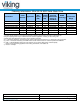
Ordering Information: Slim SATA SSD Solid-State Drive Part Number VRFEM1008GPCxMyz VRFEM1012GPCxMyz VRFEM1025GPCxMyz VRFEM1032GPCxMyz VRFEM1055GPCxMyz VRFEM1080GPCxMyz VRFEM1120GPCxMyz SATA Interface Application Raw Capacity (GB) 6Gbps 6Gbps 6Gbps 6Gbps 6Gbps 6Gbps 6Gbps Industrial Industrial Industrial Industrial Industrial Industrial Industrial 16 16 32 48 64 128 128 Useable Capacity (GB)1 8 12 25 32 55 80 120 Minimum Total User Addressable Sectors in LBA Mode 15,649,200 31,277,232 48,858,768 62,
Industrial SSD – Viking’s Industrial SSD contains sophisticated provisions to protect firmware and data from corruption due to unexpected power loss. However, a Industrial SSD by industry definition does not contain on-board capacitance. Should power fail unexpectedly, “in-flight” write data may be lost. Industrial SSD’s are best used in designs that manage power fail events at the system level. Manual PSFEM1XXXGPXXX Revision B4 www.vikingtechnology.
Product Picture(s) Slim SATA Top View Manual PSFEM1XXXGPXXX Revision B4 www.vikingtechnology.
Table of Contents 1 INTRODUCTION 10 1.1 Features 10 1.2 Block Diagram 12 1.3 SATA Interface for VRFEM1xxxGP 13 1.4 Indicator LEDs 13 2 2.1 PRODUCT SPECIFICATIONS Performance 13 13 2.2 Timing 2.2.1 STANDBY IMMEDIATE Command 14 14 2.3 Electrical Characteristics 2.3.1 Absolute Maximum Ratings 2.3.2 Supply Voltage 2.3.3 Supply Current 2.3.4 Power Consumption 15 15 15 15 16 2.4 Environmental Conditions 2.4.1 Temperature and Altitude 2.4.2 Shock and Vibration 2.4.
4.3 5 Hot Plug Support COMMAND SETS 23 24 5.1 ATA Commands 5.1.1 48-Bit Address Command Set 5.1.2 ATA General Feature Command Set 5.1.3 Device Configuration Overlay Command Set 5.1.4 General Purpose Log Command Set 5.1.5 Host Protected Area Command Set 5.1.6 Power Management Command Set 5.1.7 Security Mode Feature Set 5.1.1 S.M.A.R.T. Support 5.1.2 S.M.A.R.T. Command Set 5.1.3 S.M.A.R.T. Attributes 5.1.4 Threshold Sector 5.1.5 S.M.A.R.T.
Table of Tables Table 1-1: Slim SATA SSD Features _____________________________________________ 10 Table 2-1: Maximum Sustained Read and Write: MB/sec and IOPS _____________________ 14 Table 2-2: Timing Specifications _________________________________________________ 14 Table 2-3: STANDBY IMMEDIATE Timings ________________________________________ 14 Table 2-4: Absolute Maximum Ratings ____________________________________________ 15 Table 2-5: Operating Voltage _______________________________________________
1 Introduction Viking’s rugged designed SSD’s offer the highest flash storage reliability and performance in harsh environments such as shock, vibration, humidity, altitude, ESD, and extreme temperatures. Viking SSD’s meet JEDEC JESD22 standards and pass numerous qualifications including MIL-STDs and NEBS.
Feature AES-128 encryption in CTR mode S.M.A.R.T. command transport (SCT) technology Superior wear-leveling algorithm Intelligent flash memory block management and read disturb management Efficient error recovery Power-throttling support Thermal sensing energy management RoHS and WEEE compliant Manual PSFEM1XXXGPXXX Revision B4 www.vikingtechnology.
1.2 Block Diagram Figure 1-1: High-Level Block Diagram for VRFEM1xxP Manual PSFEM1XXXGPXXX Revision B4 www.vikingtechnology.
1.3 SATA Interface for VRFEM1xxxGP • • • The Serial ATA (SATA) interface is compliant with the SATA IO Serial ATA specification, revision 3.x that supports SATA up to 6Gbps. The SATA interface connects the host computer to the SSD subsystem. The SATA interface runs at a maximum speed of 6.0Gbps (Gigabits per second). If the host computer is unable to negotiate a speed of 6.0Gbps, the SATA interface automatically renegotiates to a speed of 3.0 or 1.5 Gbps.
Table 2-1: Maximum Sustained Read and Write: MB/sec and IOPS Access Type VRFEM1xxxGP Units Sequential Read, 128K block size Up to 500 MB/s Sequential Write, 128K block size Up to 500 MB/s Random Read, 4K block size Up to 60,000 IOPS Random Write, 4K block size Up to 20,000 IOPS Notes: 1. Performance measured using IOmeter 08 with queue depth set to 32. 2. Write Cache enabled. 3. Random IOPS cover the entire range of legal logical block addresses (LBA’s).
2.3 Electrical Characteristics 2.3.1 Absolute Maximum Ratings Values shown are stress ratings only. Functional operation outside normal operating values is not implied. Extended exposure to absolute maximum ratings may affect reliability. Table 2-4: Absolute Maximum Ratings Description Maximum Voltage Range for Vin Maximum Temperature Range Min -0.2 -40 Max 6 85 Unit V c Min 4.5 Max 5.5 Unit V 2.3.2 Supply Voltage The operating voltage is 5.0V.
2.3.4 Power Consumption All onboard power requirements of the Slim SATA are derived from the SATA 5.0V input rail. Table 2-7: Typical Power Consumption Mode VRFEM1xxxGPxx1 Unit 2.0 <0.4 W W Read/Writes Idle Notes: 1. Typical power workload: 16K block size, 50% read, 50% sequential write. Maximum power workload: 256K block size, 0% read, 100% sequential write. 2. Typical power consumption is that of a device with 64GB of physical capacity. 2.4 Environmental Conditions 2.4.
Table 2-9: Shock and Vibration Specifications Description 50g, 11ms, 3 shocks applied in each direction on 3 mutually perpendicular axes X, Y, Z Shock Vibration 2.4.3 16.4g rms 10-2,000 Hz, 3 axes Electromagnetic Immunity Slim SATA is an embedded product for host systems and is designed not to impair with system functionality or hinder system EMI/FCC compliance. 2.
2.5.1.1 DATA ECC Algorithms The following data error correction is provided: • Up to 55 bytes of redundancy applied to 512 bytes of data 2.5.1.2 Data Path CRC Error Detection CRC error detection is applied against data along internal data paths. CRC detection uses a 32-bit checksum (CRC32) to protect data along all internal data paths. 2.5.1.3 RAISETM Data Protection Against Catastrophic Flash Page/Block Failure R.A.I.S.E.
2.5.1.4 Firmware Code Protection Firmware requires special attention to ensure the code is execution-worthy. For this reason, firmware is stored in multiple redundant images in the Flash array. Image checksums are compared between all stored copies to ensure identical code. Any image not corroborated by at least one other image is discarded. In this way a reliable firmware image is always chosen on boot-up for execution.
more by erasures and writes over time. That is, it determines actual cell wear, not simply assumed wear normalized to write/erase events. The controller employs this information in its superior wear-leveling algorithm along with its ongoing record of writes and erasures, to ensure each block is impacted by P-E cycles no more than the average. The result is an SSD that is far more reliable across its full capacity and over a far greater length of time.
3 Mechanical Information Capacity (GB) Height (mm) Width (mm) Length (mm) 4.00 max 54 max 39.82 max 8 to 120 Figure 3-1: Dimensions Notes: • All dimensions are in inches [millimeters]. Manual PSFEM1XXXGPXXX Revision B4 www.vikingtechnology.
3.1 Slim SATA SSD Weight The weight of a Slim SATA (MO-297) is approximately 8.0 grams. 4 Pin and Signal Descriptions 4.1 Pin Locations Figure 4-1: Layout of Signal and Power Segment Pins Signal Segment S1 Power Segment P1 4.
Table 4-2: Serial ATA Power Pin Definitions Pin P1 P2 P3 P4 P5 P6 P7 P8 P9 P10 P11 P12 P13 P14 P15 Function 3.3V_1 3.3V_2 3.
5 Command Sets The Element SSD complies with ATA-8. All mandatory and many optional commands and features are supported. The tables below summarize the supported ATA feature set and commands. Table 5-1: ATA Feature Set Feature Set ATA-8 REF Support Element ATA Device SSD General feature set 4.2 M YES PACKET feature set 4.3 P NO 48-Bit Address feature set Advanced Power Management (APM) feature set Automatic Acoustic Management (AAM) feature set 4.4 O YES 4.5 O NO 4.
Manual PSFEM1XXXGPXXX Revision B4 www.vikingtechnology.
5.1 ATA Commands Table 5-2: ATA Commands ATA-8 REF 7.2 ATA8 N Sup p NO Key Word Option CfaEraseSec, CFES Feature Set CFA OP C0h CFA REQUEST EXTENDED ERROR CODE CFA TRANSLATE SECTOR O NO CfaReqErr, CFRE CFA 03h O NO CfaTransSec, CFTS CFA 87h O NO CfaWrMul, CFWM CFA CDh O NO CfaWrSec, CFWS CFA 38h 7.7 CFA WRITE MULTIPLE WITHOUT ERASE CFA WRITE SECTOR(S) WITHOUT ERASE CHECK MEDIA CARD TYPE O NO ChkMedType, CHMT Media Card D1h 7.
ATA-8 REF 7.20.9 7.20.1 0 7.20.1 1 7.21 Commands REMOVE LBA(S) FROM CACHED PINNED SET RETURN FROM NV CACHE POWER MODE SET NV CACHE POWER MODE ATA8 O Sup p NO Feature Set NV Cache OP B6h/11h O NO NV Cache B6h/01h O NO NV Cache B6h/00h Key Word Option NOP O YES NOP General 00h 7.22 PACKET O NO Packet, PAKT Packet A0h 7.23 READ BUFFER O YES RdBuf, RBUF General E4H 7.24 READ DMA M YES RdDma, RDMA General C8h 7.25 READ DMA EXT M YES RdDmaEx, RDMX 25h 7.
ATA-8 REF - Commands SEEK ATA8 M Sup p YES Key Word Option Feature Set OP 70h-7Fh 7.47 SERVICE O NO Service, SRVC TCQ A2h 7.48 SET FEATURES M YES SetFeature, SETF General EFh 7.49.2 SET MAX ADDRESS M YES HPA F9h 7.49.3 SET MAX FREEZE LOCK O YES SetMaxAddr, SMXA, SMAX SetMaxFrzLock, SMFL HPA F9h/04h 7.49.4 SET MAX LOCK O YES SetMaxLock, SMLK HPA F9h/02h 7.49.5 SET MAX SET PASSWORD O YES HPA F9h/01h 7.49.
ATA-8 REF 7.63 Commands WRITE DMA EXT ATA8 M Sup p YES Key Word Option WrDmaEx, WDMX Feature Set 48-bit Address 48-bit Address TCQ OP 35h 7.64 WRITE DMA FUA EXT M YES WrDmaFuaEx, WDFE 7.65 WRITE DMA QUEUED O NO WrDmaQ, WDMQ 7.66 WRITE DMA QUEUED EXT O NO WrDmaQEx, WDQX TCQ 36h 7.67 WRITE DMA QUEUE FUA EXT O NO WrDmaQFuaEx, WDQF TCQ 3Eh Obs YES - WRITE DMA (w/o retry) 3Dh CCh CBh 7.68 WRITE FPDMA QUEUED M YES 7.69 WRITE LOG EXT M YES 7.
• • • • • • • • • • • • • • • • • Download Microcode Executive Device Diagnostics Flush Cache Identify Device NOP (optional) Read Buffer (optional) Read DMA Read Multiple Read Sector(s) Read Verify Sector(s) Seek Set Features Set Multiple Mode Write Buffer (optional) Write DMA Write Multiple Write Sector(s) 5.1.
• Set Max Unlock (optional) 5.1.6 Power Management Command Set Slim SATA supports the Power Management command set consisting of: • Check Power Mode • Idle • Idle Immediate • Sleep • Standby • Standby Immediate 5.1.
The supported S.M.A.R.T. command set is listed in the table below. See the AT Attachment standard for implementation details. 5.1.2 S.M.A.R.T. Command Set The supported S.M.A.R.T. command set is listed in the table below. See the AT Attachment standard for implementation details. Table 5-3: S.M.A.R.T. Command Set Value (hex) Command 00-CF Reserved D0 S.M.A.R.T. read attributes D1* S.M.A.R.T. read threshold D2 S.M.A.R.T. enable/disable attribute autosave D3* S.M.A.R.T. save attribute values D4 S.M.A.R.T.
00h 01h 02h 04h 7Fh 81h 82h 84h Execute S.M.A.R.T. off-line routine immediately in off-line mode Execute S.M.A.R.T. Short self-test routine immediately in off-line mode Execute S.M.A.R.T. Extended self-test routine immediately in off-line mode Execute S.M.A.R.T. Selective self-test routine immediately in off-line mode Abort off-line mode self-test routine Execute S.M.A.R.T. Short self-test routine immediately in captive mode Execute S.M.A.R.T.
Handling and reporting error conditions relating to the updating of S.M.A.R.T. logs and S.M.A.R.T. Attributes is accomplished the same as handling error conditions experienced while saving user data. Likewise, handling and reporting error conditions relating to other processes (including background processes) that occur while updating S.M.A.R.T. logs and S.M.A.R.T. Attributes is accomplished the same as handling such error conditions while saving user data. S.M.A.R.T.
ID 201 Hex 0xC9 Attribute Name Uncorrectable Soft Read Error Rate 204 0xCC Soft ECC Correction Rate 231 0xE7 SSD Life Left 241 0xF1 Lifetime Writes from Host 242 0xF2 Lifetime Reads to Host Description Number of soft read errors that cannot be fixed on-the-fly and requires deep recovery via RAISE. (ie UECC) Number of errors corrected by RAISE that cannot be fixed on-the-fly and requires ECC (multilevel) to correct. (ie UECC) Indicates the approximate percentage of SSD life left.
Table 5-6: Baseline S.M.A.R.T. Attribute Details ID 1 Attribute Name Raw Read Error Rate Description Raw error rate related to ECC errors. Errors are counted as ECC errors above a threshold. For the controller, this attribute includes Uncorrectable ECC (UECC) errors, and Uncorrectable RAISE (URAISE)errors.
ID 5 Attribute Name Retired Block Count Description Tracks the total number of retired blocks. Normalized Equation: Count = 100 - (100* RBC / MRB) RBC = RetiredBlockCount = Number of retired blocks. MRB = MinimumReqBlocks = Minimum number of reserve blocks available for controller use. This value is set at factory configuration time. Rational The normalized equation for this attribute decrements as blocks are retired and the reserve (over-provisioned) block count is decremented.
ID Attribute Name Description [6-4] : None (0x00) Rational 171 Program Fail Count Counts the number of flash program failures. This Attribute returns the total number of Flash program operation failures since the drive was deployed. Usage: [3-0] : Program Error Count [6-4] : None (0x00) This Attribute is identical to Attribute 181. Counts the number of flash erase failures. This Attribute returns the total number of Flash erase operation failures since the drive was deployed.
ID 177 Attribute Name Wear Range Delta Description Provides a value equal to the delta between the max worn Flash block and the least worn Flash block, as a percentage of the max rated wear of the SSD. Rational This Attribute identifies the “delta” between most-worn and least-worn Flash blocks, as a percentage of the max rated wear of the Flash memory on the SSD. Equation: Wear Range Delta = [(MW - LW) / MRW] x 100 For 10,000-cycle Flash, where 1% of rated cycles is 100 cycles, a value of 1.
ID 187 Attribute Name Reported Uncorrectable Errors (URAISE) Description Uncorrectable Errors (URAISE) This attribute tracks the number of uncorrectable RAISE (URAISE) errors reported back to the host for all data access commands. Normalized Equation: 100 - (URAISE) Normalized Value Range: Best = 100 Worst = 1 194 Temperature Raw Usage: [1-0] : Cumulative lifetime URAISE errors [6-2] : None (0x00) Temperature of the SSD assembly. That is,the temperature inside the SSD housing.
ID 195 Attribute Name ECC On-the-Fly Error Count Description This attribute tracks the number of uncorrectable ECC errors (UECC). The normalized value is only computed when the number of bits in the "BitsRead" count is in the range of 10^10 to 10^12. The count is cleared at power on reset and when >10^12 bits have been read.
ID 196 Attribute Name Reallocation Event Count Description Tracks the total number of reallocated Flash blocks. Normalized Equation: Count = 100 - (100* RBC / MRB) RBC = RetiredBlockCount = Number of retired blocks. MRB = MinimumReqBlocks = Minimum number of reserve blocks available for contoller use. This value is set at factory configuration time. Rational The normalized equation for this attribute decrements as blocks are retired and the reserve (over-provisioned) block count is decremented.
ID Attribute Name Description Rational by this Attribute. 204 Soft ECC Correction Rate (UECC) Number of errors corrected by RAISE that cannot be fixed on-the-fly and requires RAISE to correct. The normalized value is only computed when the number of bits in the "BitsRead" count is in the range of 10^10 to 10^12. The count is cleared at power on reset and when >10^12 bits have been read. The Soft ECC Correction Rate includes all uncorrectable ECC (UECC) errors tracked by the CONTROLLER.
ID Attribute Name 241 Lifetime Writes from Host System Description Normalized Value Range: 100 = Best = Full SSD life remains 10 = Replace = Sufficient Flash blocks still in service, but rated PE Cycles consumed 1 = Worst = Insufficient Flash blocks remain in service; EOL; drive is readonly Indicates the number of bytes (in 64GB resolution) written to the drive by a host system, over the life of the drive.
Attribute Sector The S.M.A.R.T. Attribute Sector defines attribute format and the data structure is defined in the following table. Table 5-7: S.M.A.R.T. Attribute Data Structure Byte Description 0:1 2 3:4 5 6 7:12 13 14:25 S.M.A.R.T. structure version number First Stored Attribute Number (i.e.
Table 5-8: S.M.A.R.T. Threshold Data Structure Byte Description 0:1 2 3 4:13 14 15 16:25 S.M.A.R.T. structure version number First Stored Attribute Number (i.e. “1” for RawErrorRate) Threshold Value for first attribute Reserved Next Stored Attribute Number Threshold Value for next attribute Reserved Attribute Number, Threshold and 10 reserved bytes for supported attributes, (max 30 collected Attributes, including above) Reserved Vendor Unique Checksum 26:361 362:379 380:510 511 5.1.5 S.M.A.R.T.
6 Certifications and Compliance Table 6-1: Device Certifications Certification/Compliance RoHS China RoHS Serial ATA EU WEEE Compliant Description Viking Modular Solutions(TM), Sanmina Corporation ("Viking") shall use commercially reasonable efforts to provide components, parts, materials, products and processes to customers that do not contain: (i) lead, mercury, hexavalent chromium, polybrominated biphenyls (PBB) and polybrominated diphenyl ethers (PBDE) above 0.
8 Glossary This document incorporates many industry- and device-specific words. Use the following list to define a variety of terms and acronyms. Term Definition ATA ATAPI Advanced Technology Attachment Advanced Technology Attachment Packet Interface Bit error rate, or percentage of bits that have errors relative to the total number of bits received Device Initiated Link Power Management. The ability of the device to request SATA link power state changes.