
Instruction Manual

DRIVESYSTEMS
SOLID SHAFT CONNECTIONS
RETAIN FOR FUTURE USE
U10250 - 1 of 2
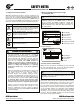
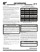
1. Solid shaft diameter tolerance
Reducer input and output shaft extensions have a diameter
tolerance as specified in Table 1.
Table 1: Solid Shaft Diameter Tolerance
Above
ø (in)
To &
Including
ø (in)
Tolerance
(in)
0.375 1.750 +0.0000 / -0.0005
1.750 7.500 +0.0000 / -0.0010
Above
ø (mm)
To &
Including
ø (mm)
Tolerance
(mm)
ISO 286-2
Fit Class
10 18 +0.012 / +0.001 k6
18 30 +0.015 / +0.002 k6
30 50 +0.018 / +0.002 k6
50 80 +0.030 / +0.011 m6
80 120 +0.035 / +0.013 m6
120 180 +0.040 / +0.015 m6
180 190 +0.046 / +0.017 m6
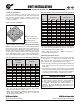
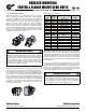
2. Fitting drive elements onto the reducer solid shaft
Solid input and output shaft extensions are provided with a
drill and tap feature as indicated in Table 2. When installing
drive elements such as coupling hubs, pulleys, sprockets, or
gears, NORD recommends using the threaded hole in the
end of the shaft, along with a suitable assembly device fitted
into the threaded hole.
Typical Assembly
Device
Table 2: Solid Shaft End - Threaded Holes
Above
ø (in)
To &
Including
ø (in)
Tap size & Depth
(in)
0.375 0.500 10-24 x 0.43 in
0.500 0.875 1/4-20 x 0.59 in
0.875 0.938 5/16-18 x 0.71 in
0.938 1.100 3/8-16 x 0.87 in
1.100 1.300 1/2-13 x 1.10 in
1.300 1.875 5/8-11 x 1.42 in
1.875 3.500 3/4-10 x 1.73 in
3.500 7.500 1-8 x 2.20 in
Above
ø (mm)
To &
Including
ø (mm)
Tap Size & Depth
(mm)
10 13 M4 x 10 mm
13 16 M5 x 12.5 mm
16 21 M6 x 16 mm
21 24 M8 x 19 mm
24 30 M10 x 22 mm
30 38 M12 x 28 mm
38 50 M16 x 36 mm
50 85 M20 x 42 mm
85 130 M24 x 50 mm
130 190 M30 x 60 mm
STOP
HARMFUL SITUATION
STOP
DO NOT DRIVE or HAMMER the coupling hub, pulley,
sprocket, or gear into place. An endwise blow to the
reducer shaft can generate damaging axial forces and
cause damage to the reducer housing, bearings or internal
components.
WARNING
To avoid serious injury the user must provide suitable
safety guards for all rotating shafts and shaft compo-
nents such as couplings, chain drives, belt drives, etc. All
guarding must adhere to local regulations and safety
standards.
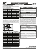
3. Installing interference-fit hubs to the reducer shaft
Prior to installing any interference-fit hubs to the reducer
shaft, consult with the manufacturer to determine proper
assembly and fit. Interference-fits usually require heating the
coupling, sprocket or gear hub, per the manufacturer’s rec-
ommendations. Coupling hub installation typically follows
ANSI/AGMA 9002-A86. Always make sure the reducer shaft
seals are protected from the heat source. Apply uniform heat
to the drive element hub to prevent distortion. NORD does
not recommend heating the drive element hub beyond 212°F
to 275°F (100°C to 135° C).
WARNING
When using heat to mount a drive element hub, do not
use open flame in a combustible atmosphere or near
flammable materials. Use suitable protection to avoid
burns or serious injury.
STOP
HARMFUL SITUATION
STOP
When using external chain or belt drives, make sure
the reducer is sized so that the shaft and bearings have
adequate capacity. To avoid unnecessary bearing loads
and additional shaft deflection, mount all power take-off
devices (sprockets, pulleys, etc.) so that the applied load
center is as close to the gear housing as possible and check
component alignment and tension of any belts or chains
per the manufacturer’s recommendation. Do not over
tighten the belts or chains.
www.nord.com/docs06.09.09
NORD Gear Corporation
Toll Free in the United States: 888.314.6673
NORD Gear Limited
Toll Free in Canada: 800.668.4378