
Instruction Manual

DRIVESYSTEMS
REDUCER MOUNTING
FOOTED & FLANGE MOUNT GEAR UNITS
RETAIN FOR FUTURE USE
U10500 - 1 of 2
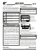
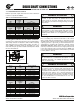
1. Foot-mounted reducers
When installing the foot-mounted gear unit, observe the
flatness specifications and bolt tightening torque guidelines
provided in U10060 and make sure the mating mounting
surface and reducer feet are clean and free of debris. Use
of shims under the feet of the gear unit may be required in
order to align the output shaft to the driven equipment.
Make sure that all feet are supported so that the housing
will not distort when it is bolted down. Improper shimming
will cause mis-alignment and may reduce the life of the gear
unit or cause component failure. Dowel pins may be field-
installed to help prevent misalignment and ensure proper
realignment if removed for service.
IMPORTANT NOTE
Gear units may be subjected to radial loads or side pull,
caused by external chain drives or belt drives. In these
instances it is recommended that the mounting base be
designed with a slide-plate adjustment to accommodate
extra slack in the chain or the belt after the feet are
loosened. When using an external chain or belt drive,
make sure the reducer is sized so that the shaft and
bearings have adequate capacity.
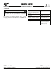
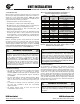
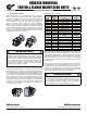
2. Flange-mounted reducers (with B5 flange)
When using the B5 flange to mount the gear unit, the bulk
head plate must be engineered to minimize buckling distor-
tions and support the cantilevered weight of the gear reduc-
er or gearmotor. On the B5 mounting flange NORD provides
a pilot register or and the flange pilot tolerance as listed per
Table 1. When the mating hole is designed with the proper
fit, the flange pilot tenon provides a means of accurately po-
sitioning the reducer while the hold-down bolts are properly
secured; once the reducer is secured, the tenon helps prevent
movement of the reducer and it helps locate the center of
the reducer output shaft.
Table : Flange Pilot Tolerance
Above
ø (in)
To &
Including
ø (in)
Tolerance
(in)
ISO 286-2
Fit Class
1.969 3.150 +0.0005 / -0.0003 j6
3.150 4.724 +0.0005 / -0.0004 j6
4.724 7.087 +0.0006 / -0.0004 j6
7.087 9.055 +0.0000 / -0.0005 h6
9.055 9.843 +0.0000 / -0.0011 h6
9.843 12.402 +0.0000 / -0.0013 h6
12.402 15.748 +0.0000 / -0.0014 h6
15.748 19.685 +0.0000 / -0.0016 h6
Above
ø (mm)
To &
Including
ø (mm)
Tolerance
(mm)
ISO 286-2
Fit Class
50 80 +0.012 / -0.007 j6
80 120 +0.013 / -0.009 j6
120 180 +0.014 / -0.011 j6
180 230 +0.000 / -0.013 h6
230 250 +0.000 / -0.029 h6
250 315 +0.000 / -0.032 h6
315 400 +0.000 / -0.036 h6
400 500 +0.000 / -0.040 h6
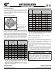
When installing the flange mounted gear unit, observe the
flatness specifications and bolt tightening torque guidelines
provided in U10060. Make sure the mating mounting surface
and reducer flange are clean and free of debris. Use a straight
edge or parallel bar to check for high spots on the mating
mounting surface and remove any raised material around the
mounting holes.
Set the gear unit into place and tighten the bolts until they
are snug. Before final bolt-tightening check for any mate-
rial gaps between the mating surfaces and if shimming is re-
quired, use “U” shaped shims at least 2 times the width of the
bolt. Avoid over shimming a very irregular surface as this will
make it very difficult to achieve proper alignment.
IMPORTANT NOTE
For heavy shock applications, it is advisable to field-in-
stall dowel pins through the mounting flange connec-
tion (in addition to the mounting bolts). This will help
control flange movement or flange rotation and relieve
the mounting bolts from this additional stress.
www.nord.com/docs06.09.09
NORD Gear Corporation
Toll Free in the United States: 888.314.6673
NORD Gear Limited
Toll Free in Canada: 800.668.4378